Fuel Charging Assembly, Replace
Fig. 18 Applying RTV sealer for intake manifold installation. V8-302 engine:
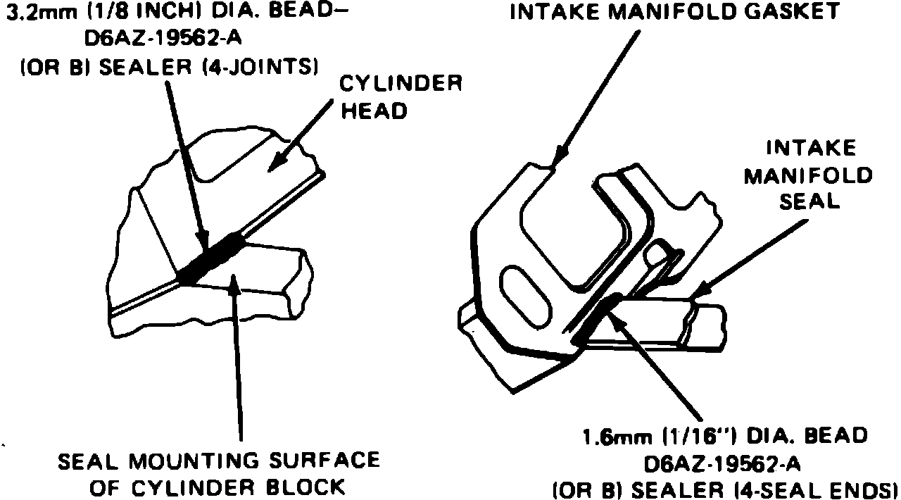
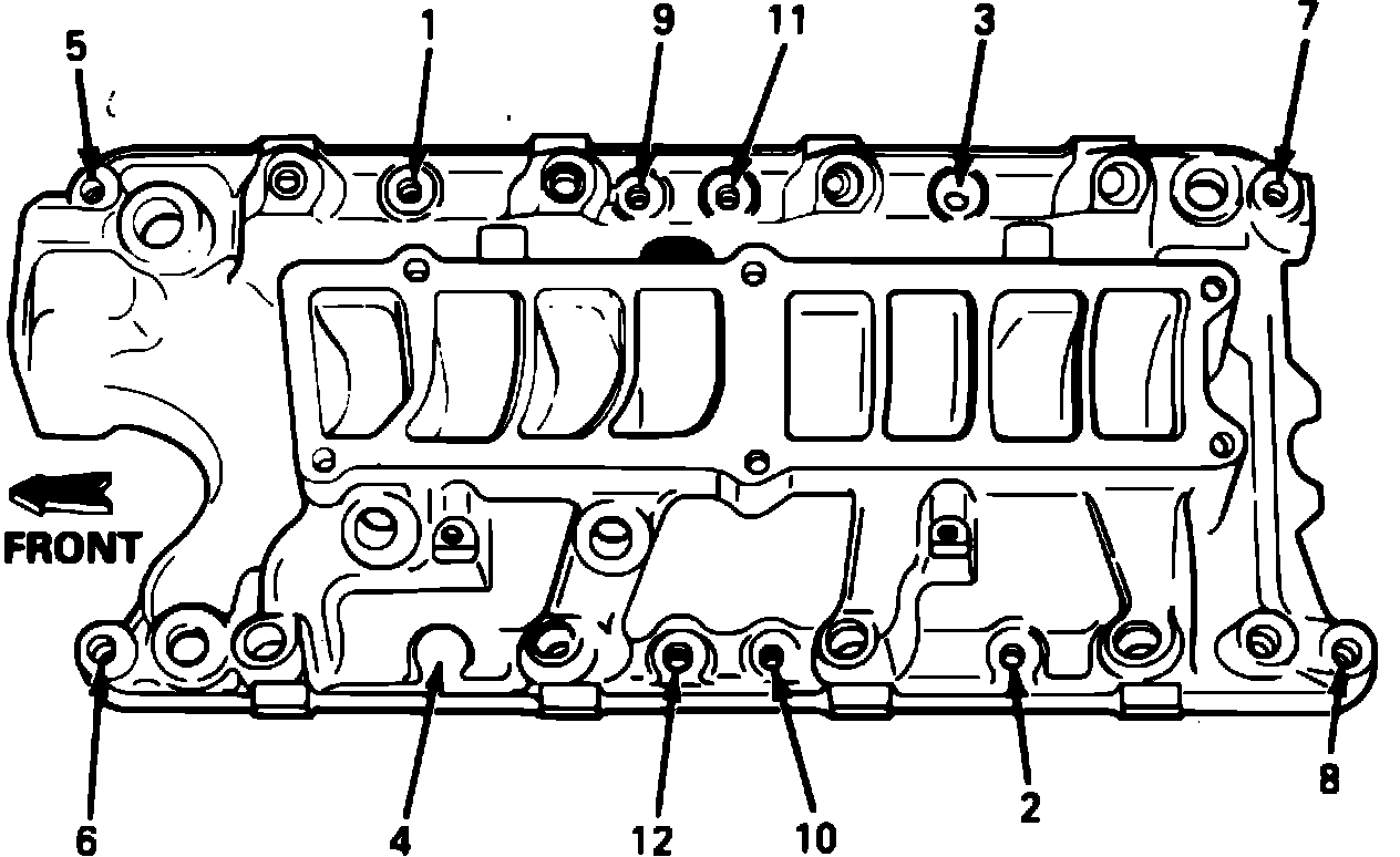
Fig. 19 Lower intake manifold bolt tightening sequence. V8-302 engine:
V8-302 Engine
1. Disconnect battery ground cable.
2. Disconnect air bypass valve, throttle position sensor and EGR position sensor electrical connector.
3. Disconnect throttle linkage at throttle ball and automatic overdrive transmission linkage from throttle body.
4. Remove throttle linkage bracket attaching bolts, then position bracket with cables to one side.
5. Disconnect upper intake manifold vacuum lines from vacuum tree, then the vacuum lines from EGR valve and fuel pressure regulator.
6. Disconnect PCV system hose from fitting on rear of upper manifold.
7. Remove two canister purge lines from throttle body.
8. On 1986 models, disconnect water heater lines from throttle body.
9. On all models, disconnect EGR tube from EGR valve.
10. Remove upper intake manifold attaching bolts, then the upper intake manifold and throttle body as an assembly.
11. Remove distributor assembly, cap and wires. Mark position of distributor and rotor prior to removal so they can be installed in their original position.
12. Disconnect electrical connectors at the Engine Coolant Temperature sensor (ECT), engine temperature sending unit, Air Charge Temperature sensor (ACT), and knock sensor.
13. Disconnect fuel injector wiring harness from main harness assembly.
14. Remove Exhaust Gas Oxygen sensor (EGO) ground wire from intake manifold stud. The plated stud and ground wire should be installed in the same position as which it was removed.
15. Disconnect fuel supply and return lines from fuel rails, then the upper radiator hose from thermostat housing.
16. Remove water bypass hose, then the heater outlet hose at intake manifold.
17. Remove three air cleaner bracket attaching nuts, then the air cleaner bracket.
18. Remove coil bracket attaching nut and position bracket to one side.
19. Remove lower intake manifold attaching studs and bolts, then the lower intake manifold assembly.
20. Reverse procedure to install, noting the following:
a. Before installing lower intake manifold, apply {1/8} inch bead of silicone rubber sealer DAZ-19562-A or equivalent at mating surfaces of intake manifold, cylinder heads and cylinder block, Fig. 18. Also apply a {1/16} inch bead of sealer to the outer end of intake manifold seal for the full width of the seal.
b. Install new end seals on the cylinder block and new gaskets on the cylinder heads. Ensure gaskets interlock with seal tabs.
c. Torque lower intake manifold attaching bolts and studs to 23 - 25 ft. lbs. in the sequence shown in Fig. 19.
d. Torque upper intake manifold attaching bolts to 15 - 22 ft. lbs.