Part 1
Transmission
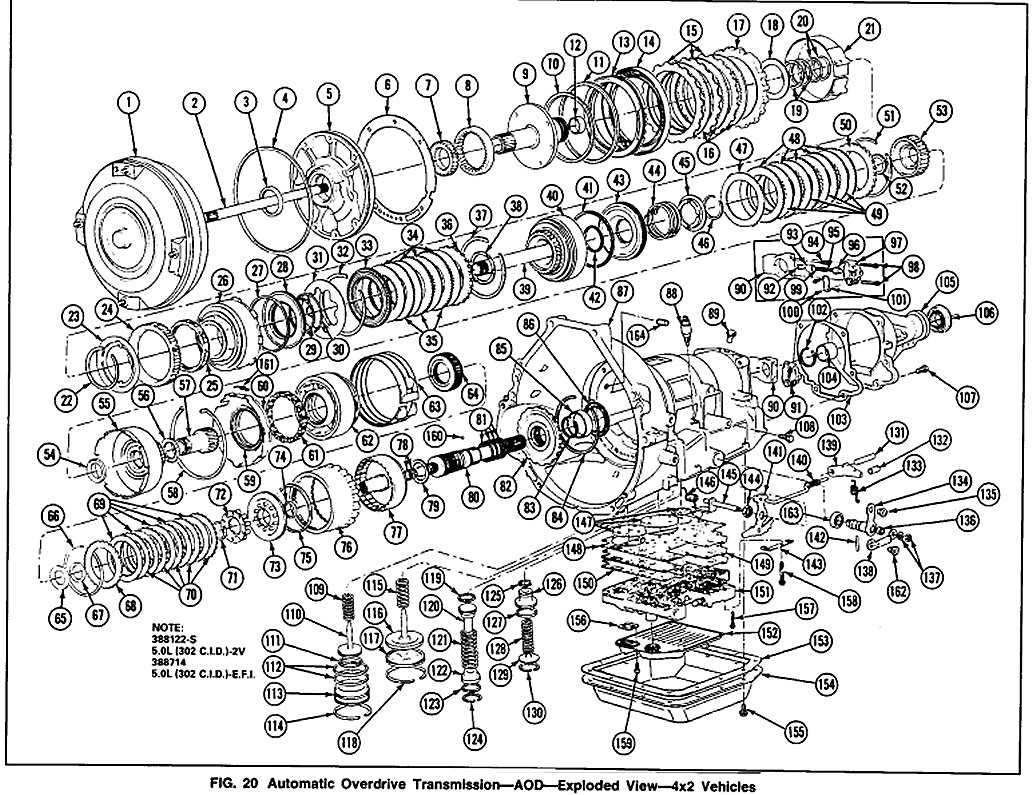
Fig. 20
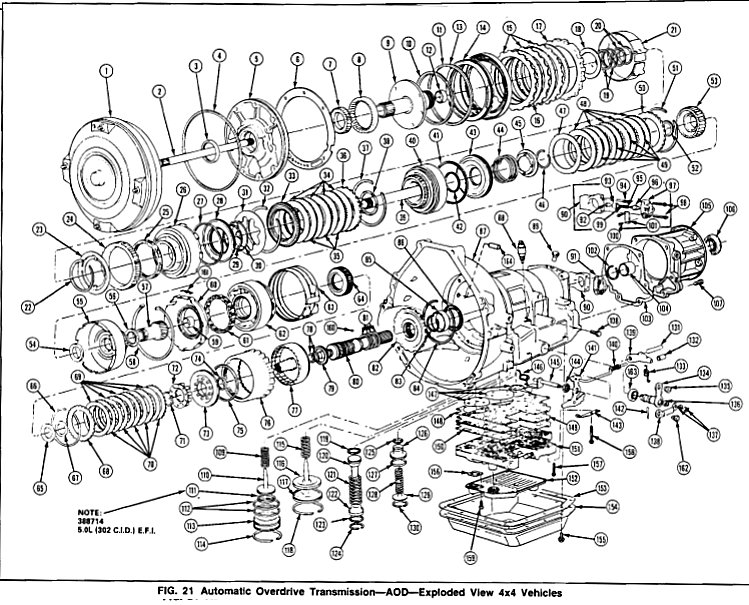
Fig. 21
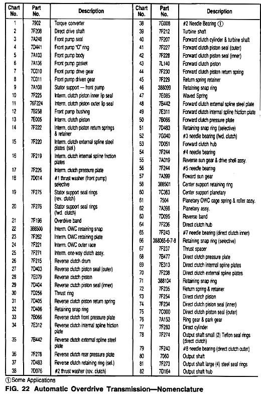
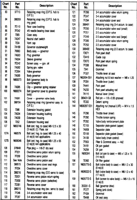
Fig. 22 Charts
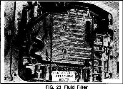
Fig. 23
Refer 10 Figs. 21-23.
Assembly
1. Install the No.9 output shaft needle bearing in the transmission case.
2. Install the bearing support, No.7 needle bearing and direct clutch hub in the direct clutch.
3. Install the output shaft, the ring gear and the direct clutch as an assembly. This assembly must be assembled as follows:
a. Assemble output shaft hub to output shaft with retaining ring (seal rings already installed).
b. Put No. 8 needle bearing in place on rear of direct clutch cylinder.
c. Slide output shaft into direct clutch cylinder.
d. Attach output shaft hub to ring gear with retaining ring.
4. Install the governor drive ball, the governor assembly and the governor retaining ring. Make sure that the face of the governor body is about flush with the counterweight. The cover and attaching screws must face forward in the case.
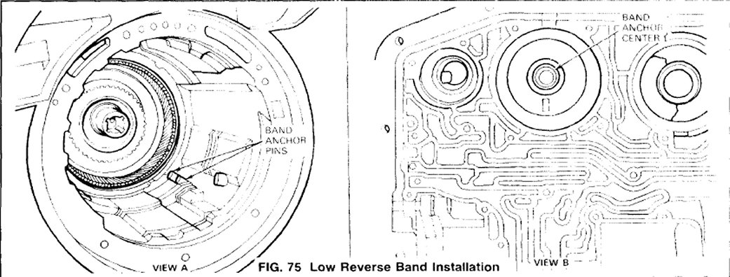
5. Install the low-reverse band. Make sure the band is seated on the anchor pins (View A, Fig. 75).
NOTE: When properly installed, the center of the band anchor can be seen through the servo piston bore (View B, Fig. 75).
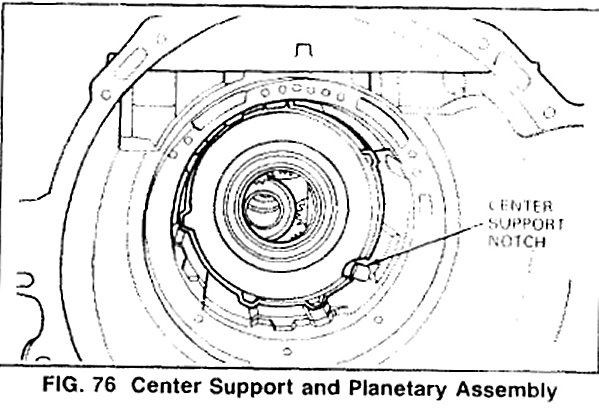
6. Install the center support and planetary assembly. Rotate the output shaft, if necessary, to align the planet carrier splines with the direct clutch hub splines.
NOTE: The planet carrier and center support assembly cannot be installed unless the notch cut in the center support is aligned with the overdrive band anchor pin (Fig. 76).
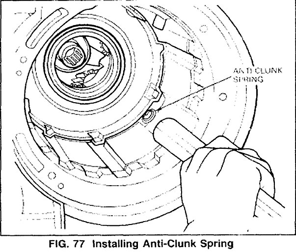
7. Install the center support anti-clunk spring using a hammer handle or wooden dowel in position shown in Fig. 77.
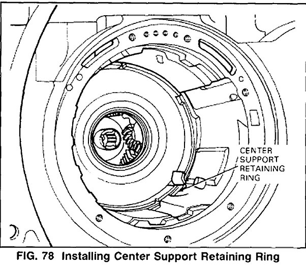
8. Install the center support retaining ring in position shown in Fig. 78
9. To determine the correct length of the servo low-reverse pin proceed as follows:
a. Install the low-reverse servo piston and return spring. Do not install the piston cover or retaining ring.
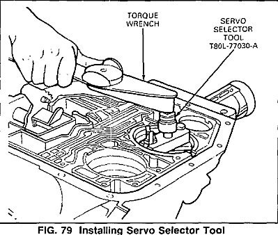
b. Install servo selector Tool T8OL-77030-A and tighten the band apply bolt on Tool T8OL-77030-A to 5.6 N.m (50 in-lbs) (Fig. 79).
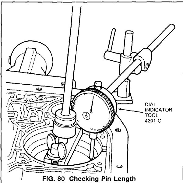
c. Attach a dial indicator, TOOL-4201and position the indicator stem on the flat portion of the piston, zero the dial indicator (Fig. 80).
d. Thread the bolt out of the selector tool until the piston stops against the bottom of the tool.
e. Read the amount of piston travel on the dial indicator.
^ If the travel is 2.845-6.O2Omm (0.112-0.237 inch) the piston length is within specification.
^ If the travel is not within specification selective pistons are available in the following lengths:
I.D.
1. 2.936--1 groove
2. 2.989--2 grooves
3. 3.043--3 grooves
Length of rod measured from piston surface to end of rod.
Select the proper rod to bring the servo piston travel within specification.
f. Remove the servo selection tool and dial indicator.
g. Install the servo cover and retaining ring.
10. Install the reverse clutch on the forward clutch.
NOTE:Make sure the No.2 needle bearing (4x2) or No.2 thrust washer (4x4) is in position.
11. Install the No.3 needle bearing and forward clutch hub in the forward clutch.
12. Position the No.4 needle bearing on the forward clutch hub and install the drive shell.
13. Install the No.5 needle bearing and forward sun gear on the drive shell.
14. Install the drive shell, forward clutch and reverse clutch as an assembly. Rotate the output shaft, as necessary, to aid the engagement of the sun gear with the planetary gears.
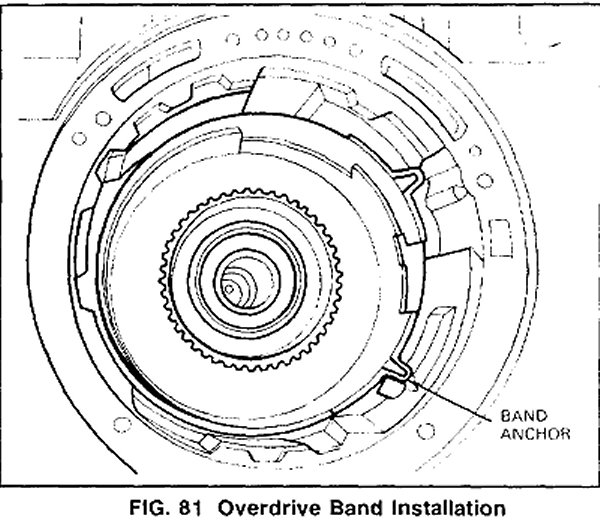
15. lnstall the overdrive band. Make sure the band anchor is properly positioned on the anchor pin as shown in Fig. 81.
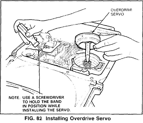
16. Install the overdrive servo (Fig. 82).