Valve Body
Valve Body
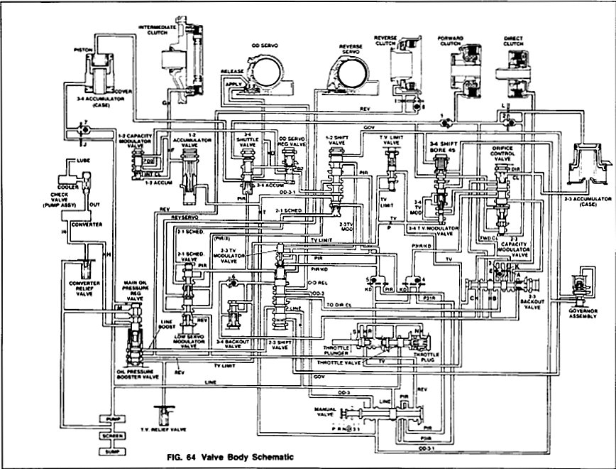
Refer to Fig. 64.
Disassembly
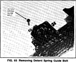
Fig. 65
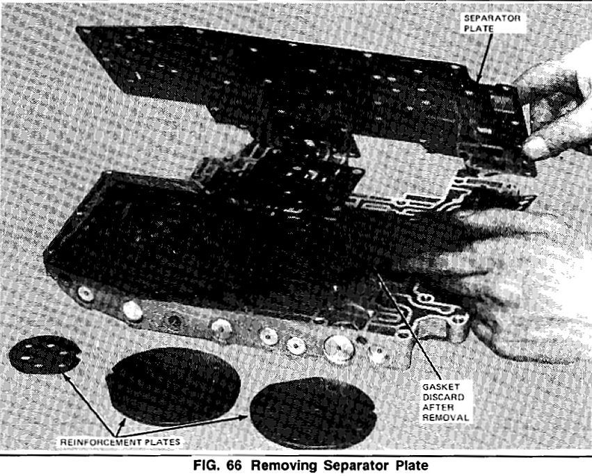
Fig. 66
1. Remove and discard valve body gasket. Loosen and remove (11) bolts (1Omm socket) from reinforcement plates and detent spring guide bolt(8mm) from separator plate (Fig. 65). Remove separator plate, reinforcement plates and separator plate gasket (Fig. 66). Discard gasket.
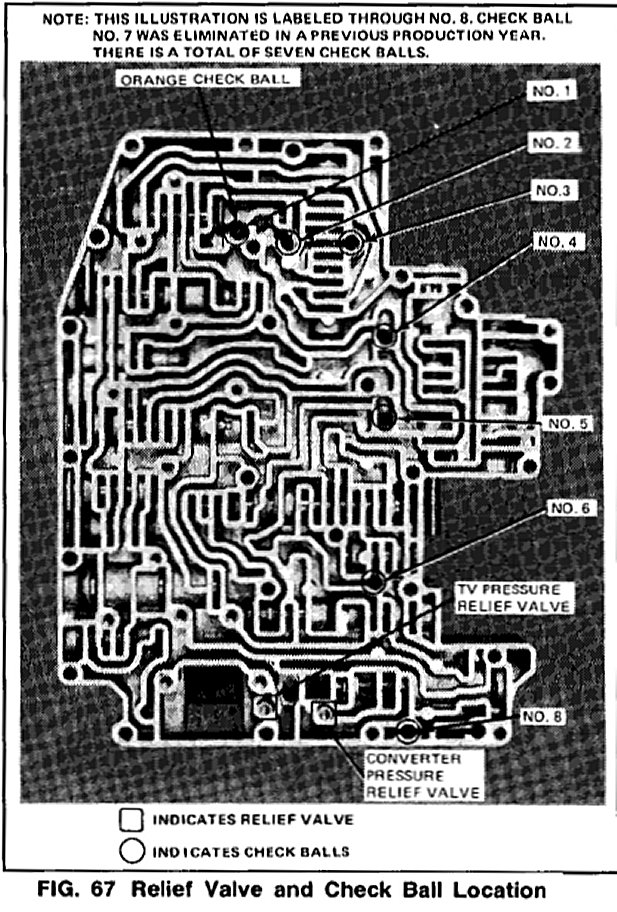
Fig. 67
2. Remove the two relief valves and seven check balls from the valve body. Note the location of the orange ball. It is not interchangeable with the (6) black balls (Fig. 67).
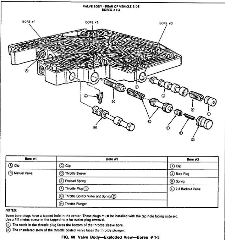
Fig. 68
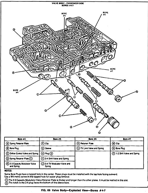
Fig. 69
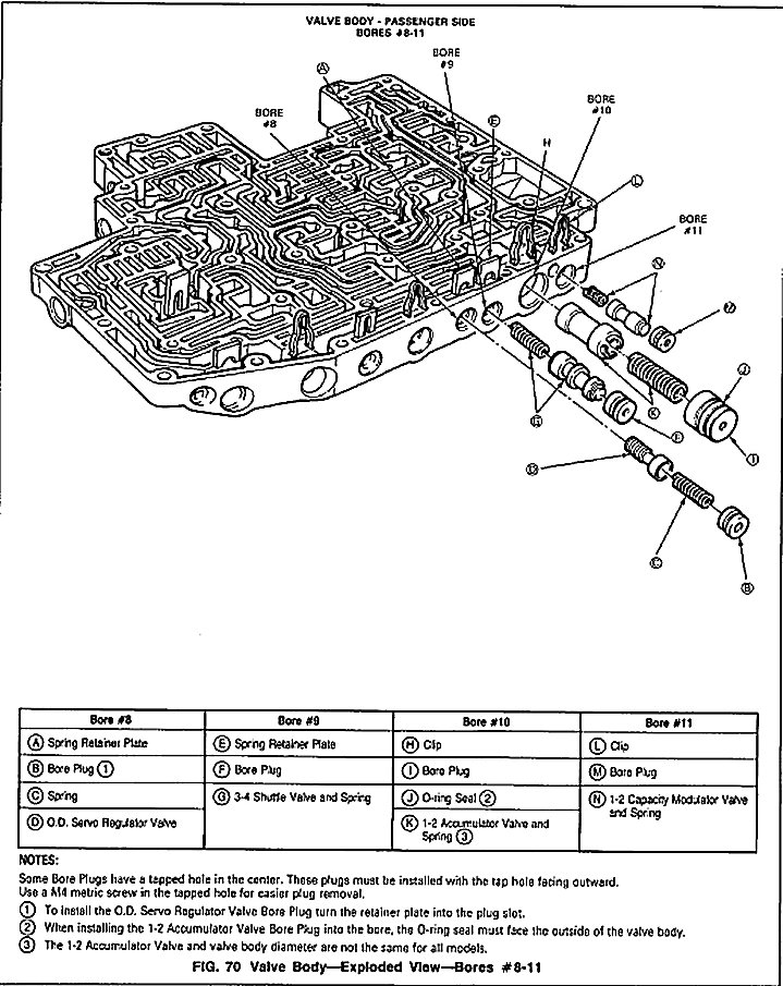
Fig. 70
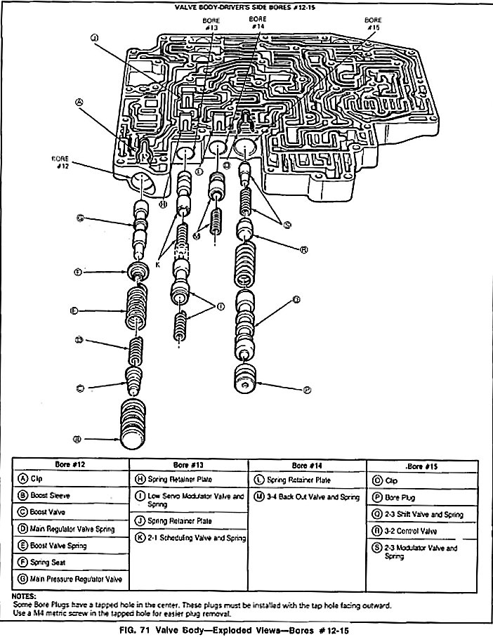
Fig. 71
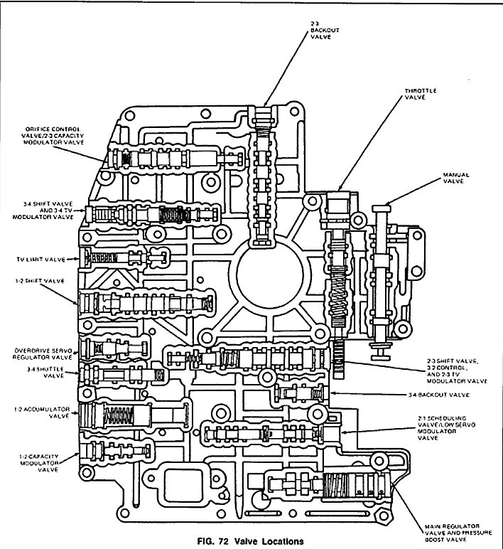
Fig. 72
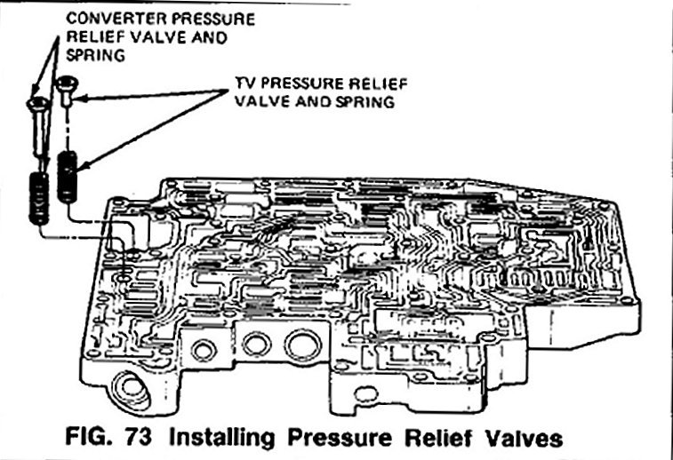
Fig. 73
3. Refer to Figs. 68-72 for identification and location of all valves in the valve body. Figs. 70-73 shows all valves in an exploded view. Fig. 72 shows all valve components assembled in the correct location in the valve body.
NOTE: Most main control valve body plugs have tapped holes on the outside to accommodate a metric (M4) screw for easier removal of the plugs when cleaning or servicing the valve body. Reinstall the plugs with the tapped holes on the outside.
4. Remove the manual valve from the valve body.
5. With an awl or ice-pick, lift the retaining clip off the throttle sleeve. Press the throttle plunger into the bore and spring pressure will force the throttle sleeve out of the valve body. Position a finger to prevent the valves from flying out of the bore. Remove the throttle sleeve, preload spring, throttle plug, throttle control valve, throttle control spring and throttle plunger.
NOTE: The chamfered stem of the throttle control valve faces the throttle plunger. The notch in the throttle plug faces the bottom of the sleeve bore.
6. Lift the retaining clip oft the 2-3 backout valve with an awl or ice-pick. Remove the bore plug, spring and 2-3 backout valve.
7. Remove the retaining plate from the bore plug of the orifice control valve. Remove the bore plug, spring, orifice control valve and spring. With needle- nose pliers, remove the spring retaining plate that separates the orifice control valve from the 2-3 capacity modulator valve. This retainer plate is longer and thicker than the other four spring retainer plates and must be reinstalled in this slot. Remove the modulator valve spring and 2-3 capacity modulator valve.
8. Lift the retaining clip off the 3-4 shift valve sleeve. Remove the sleeve, plug, 3-4 shift valve, spring, modulator valve spring and 3-4 TV modulator valve.
NOTE: The notch in the plug faces the bottom of the sleeve bore.
9. With needle-nose pliers, remove the spring retaining plate from the TV limit valve bore. Remove the spring and TV limit valve.
10. Remove the retaining clip from the 1-2 shift valve bore plug. Remove the bore plug, 1-2 shift valve and spring.
11. Remove plug retaining plate from the O.D. servo regulator valve bore plug. Remove the bore plug, spring and O.D. servo regulator valve.
12. Lift the retaining plate oft the 3-4 shuttle valve bore plug. Remove the bore plug, 3-4 shuttle valve and spring.
13. With an awl or ice pick, lift the retaining clip off the 1-2 accumulator valve bore plug. Remove the bore plug, 0-ring seal, spring and 1-2 accumulator valve.
NOTE: The 1-2 accumulator valve and valve body diameter are not the same for all models.
14. Remove the retaining clip from the 1-2 capacity modulator valve bore plug. Remove the bore plug, 1-2 capacity modulator valve and spring.
15. Remove the retaining clip from the boost sleeve. Remove the boost sleeve, boost valve, main regulator valve spring, boost valve spring, spring seat and main pressure regulator valve.
16. Two spring retainer plates hold and separate the 2-1 scheduling valve and the low servo modulator valve. Remove the Outer spring retainer plate and low servo modulator spring and valve from the valve body. Remove the modulator valve spring, low servo modulator valve, scheduling valve spring and the 2-1 scheduling valve.
17. With needle-nose pliers, remove the spring retainer plate from the 3-4 backout valve bore. Remove the spring and 3-4 backout valve.
18. Remove the retaining clip from the 2-3 shift valve bore plug. Remove the bore plug, 2-3 shift valve, the 3-2 control valve, the shift valve spring, modulator valve spring, and 2-3 TV modulator valve.
19. Inspect and clean the valve body as described in Section 17-01, General Automatic Transmission Service, under Control Valve Body-Cleaning and Inspection.
Assembly
Before installing the control valves, lubricate the bores, valves, springs and seals with clean transmission fluid.
Fig. 68
Fig. 69
Fig. 70
Fig. 71
Fig. 72
Refer to Figs. 68-71 for correct assembly of all valve components. Refer to Fig. 72 for correct location of the valves in the body.
1. Insert the 2-3 TV modulator valve, modulator valve spring, shift valve spring, the 3-2 control valve, and 2-3 shift valve in the valve body. Insert the bore plug and from the underside of the body place the retaining clip in the slot on the bore plug.
2. Install the 3-4 backout valve and spring in the valve body. Insert the spring retainer plate in the proper slot in the valve body.
3. Place the 2-1 scheduling valve and spring in the valve body. Install the spring retainer plate in the bore. Install the low servo modulator valve and spring into the bore in front of the retainer plate that separates the scheduling valve from the modulator valve. Insert the retaining clip into the proper slot in the valve body.
4. Install the main pressure regulator valve, spring seat, boost valve spring, main regulator valve spring, boost valve and boost sleeve. Install the retaining clip on the boost sleeve.
5. Install spring, 1-2 capacity modulator valve, and bore plug in the valve body. Place retaining clip on bore plug.
6. Install the 1-2 accumulator valve, and spring. Install the 0-ring in the shallow groove of the bore plug and lubricate the 0-ring. Install the bore plug into the bore with the 0-ring toward the outside. Install the retaining clip on the bore plug.
NOTE: The 1-2 accumulator valve and valve body diameters are not the same for all models.
7. Insert the spring, 3-4 shuttle valve, and bore plug in the valve body. Place retaining plate on bore plug.
8. Install the O.D. servo regulator valve, spring and bore plug into bore. Install the bore plug by turning the plate into the slot of the bore plug.
9. Place spring, 1-2 shift valve, and bore plug into valve body. Install retaining clip on bore plug.
10. Insert TV limit valve and spring into valve body bore. Insert spring retainer plate in slot of valve body bore.
11. Install 34 TV modulator valve and spring, 3-4 shift valve and spring, plug and sleeve in valve body. Place retaining clip on sleeve. NOTE: The notch in the plug laces the bottom of the sleeve bore.
12. Place 2-3 capacity modulator valve and spring in bore. Install the spring retainer plate that separates the 2-3 capacity modulator valve and orifice control valve.
NOTE: The spring retainer plate is thicker and longer than the other four retainer plates. Insert orifice control valve and spring, and bore plug in front of retainer plate. Install retaining plate on bore plug.
13. Install 2-3 backout valve, spring and bore plug in valve body. Install retaining clip on bore plug.
14. Install throttle plunger, throttle control spring, and throttle control valve.
NOTE: The chamfered stem of the throttle control valve faces the throttle plunger.
15. Assemble the preload spring and throttle plug into the throttle sleeve, then load this assembly into the bore. Hold the sleeve into the bore and install the retaining clip from the opposite (unfinished) side of the valve body.
NOTE: The notch In the throttle plug faces the bottom of the sleeve bore.
16. Install the manual valve in the valve body bore.
Fig. 67
17. Install the valve body check balls (Fig. 67).
Note: the location of the orange ball. This ball is larger than the others and is not interchangeable.
Fig. 67
Fig. 73
18. Install the pressure relief valves (Figs. 67 and 73).
19. Install Alignment Pins T8OL-77100-A (Fig. 73). Note the location of the pins. These two holes are smaller than the other bolt holes to assure proper alignment of gasket and separator plate with valve body. These two holes also align the valve body gasket and valve body assembly with the case.
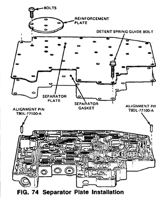
Fig. 74
20. Use a new separator plate gasket. Slide the gasket and the separator plate over the two alignment pins. Position the (3) reinforcement plates and loosely install the (11) bolts (Fig. 74). Loosely install the detent spring guide bolt. (This bolt is the same as the short valve body assembly to case attaching bolts).
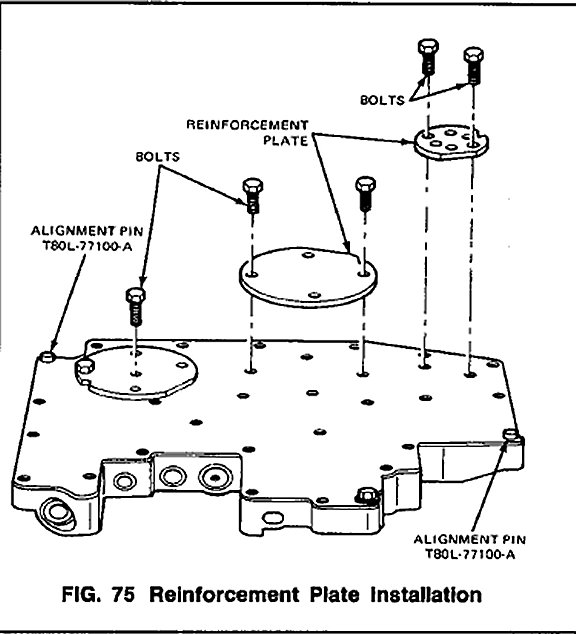
Fig. 75
21. Starting at the center (large) reinforcement plate and working outward, tighten the eleven 1Omm bolts to specification (Fig. 75). Then tighten the 8mm detent spring guide bolt to specification. Remove the alignment pins.