Manual and Throttle Linkage
Manual end Throttle Linkage
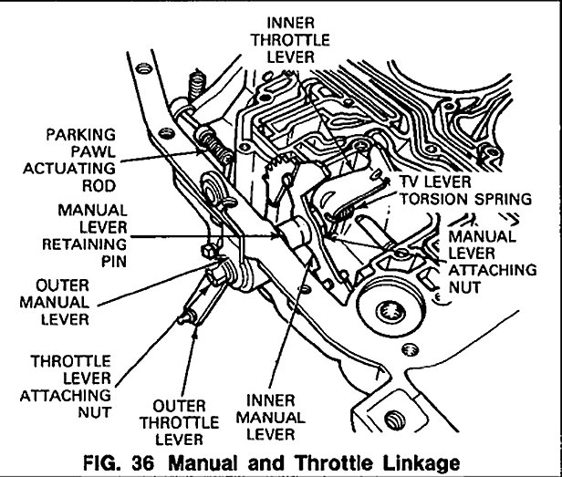
Refer to Fig. 36.
Disassembly
1. Grasp the outer throttle lever firmly and loosen the lever attaching nut (13mm). Remove the attaching nut, the lockwasher, and throttle lever.
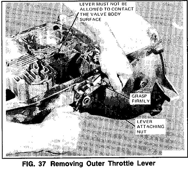
NOTE: The outer throttle lever must be held in the position shown in Fig. 37 to prevent the inner throttle lever from rotating against the machined valve body surface. Failure to observe this precaution could result in damage to the valve body surface.
2. Using a small screw driver or awl, remove the seal from the outer manual lever counterbore. Discard seal.
3. Using a pair of diagonal cutters, remove the manual shaft retaining pin from the case.
4. Grip the inner manual lever with an adjustable wrench and loosen the lever attaching nut (2Omm). Thread the nut off the shaft and remove the lever.
5. Remove the inner throttle lever and torsion spring.
6. Remove the inner manual lever and parking paw actuating rod as an assembly. After removal, the rod may be disengaged from the lever.
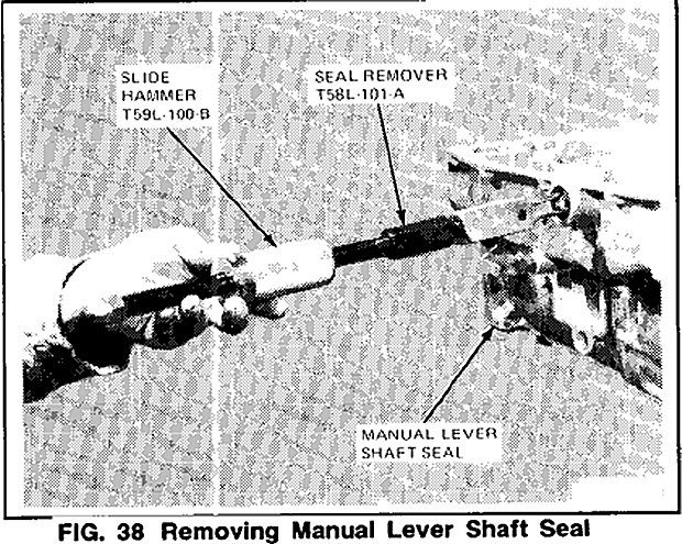
7. Remove the manual lever shaft seal from the case using seal remover Tool T58L-101-A (or equivalent) and Slide Hammer T59L100-B (or equivalent) as shown in Fig. 38. Discard seal.
Assembly
To assemble the manual and throttle linkages, reverse the disassembly except for the following:
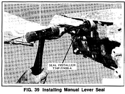
1. Install a new manual lever seal using Seal Installer T74P-77498-A or equivalent tool as shown in Fig. 39.
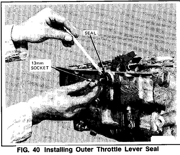
2. Before installing the outer throttle lever, install a new seal in the outer manual lever (Fig. 40). A 13mm thin wall socket may be useful, using the end that the ratchet drive would be inserted into, to seat the seal.
NOTE: The seal identification number must face outward.