Forward Clutch
Forward Clutch
Disassembly
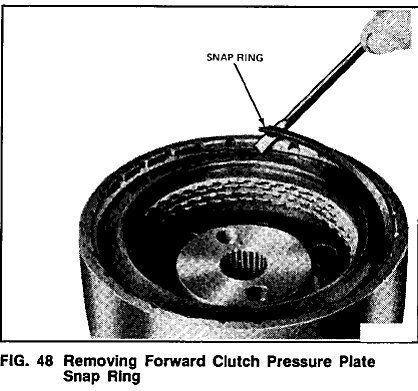
1. Remove the clutch pressure plate snap ring (Fig.48).
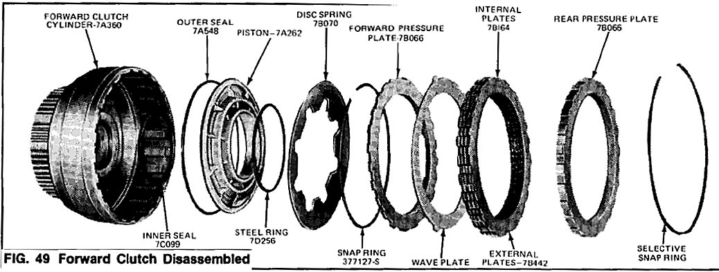
2. Remove the rear pressure plate, the drive and driven plates, wave plate, and the forward pressure plate from the clutch hub (Fig. 49).
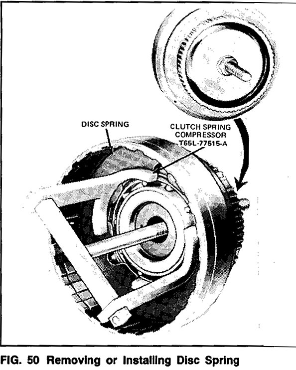
3. Remove the snap ring (Fig. 50) that secures the disc spring in the clutch cylinder. Remove the disc spring using Tool T65L-77515-A.
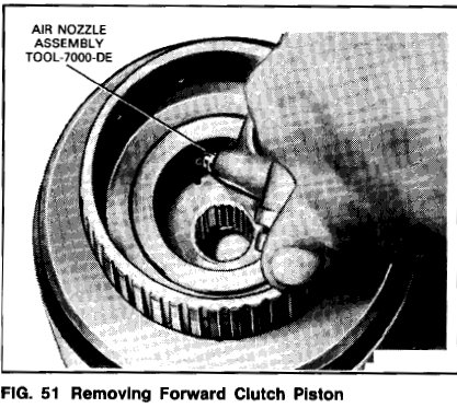
4. Apply air pressure to the clutch cylinder using TOOL-7000-DE (Fig. 51) to remove the piston.
5. Remove the seal from the piston and the seal from the clutch hub (Fig. 49).
Assembly
1. Dip two new seals in transmission fluid. Install the smaller seal on the clutch hub and the lip seal on the clutch piston.
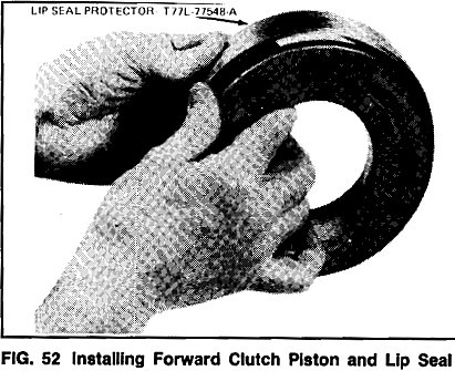
2. Install the clutch piston and lip seal with Lip Seal Protector, T77L-77548-A, (Fig. 52).
3. Position the installation tool into the forward clutch cylinder, so that the bore of the tool is aligned with the piston bore in the cylinder. Press the piston into the cylinder until it bottoms in the bore. Remove the installation tool.
4. Make sure that the steel pressure ring is in the groove on the piston. Position the disc spring In the cylinder with the dished face downward. Install the spring as shown in Fig. 50 so that the pressure ring and spring are in contact. Secure the disc with the retaining snap ring.
5. Install the forward pressure plate with the flat side up and the beveled side downward. Dip the clutch plates in clean transmission fluid (Specification DEXRON� II Series D or equivalent). Next, install the wave plate, then a steel plate and a composition driven plate. Install the remaining plates in this ) sequence (Fig. 49). Refer to the Specification, Specificationsfor the number of plates required. The last plate installed will be the rear pressure plate. Install the snap ring and make certain that it seats fully in the groove.
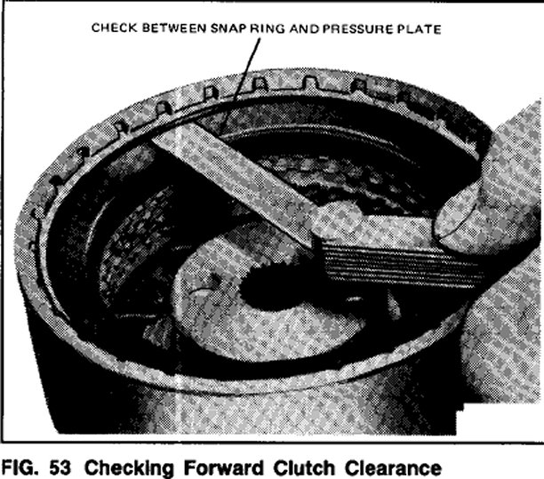
6. With a feeler gauge, check the clearance between the snap ring and the pressure plate (Fig. 53). Downward pressure on the plate should be maintained when making this check. Clearance e should be 0.533-1.168mm (0.021-0.046 inch).
7. if the clearance is not within specifications, selective snap rings are available in the following thicknesses:
1.42-1.52mm (0.056-0.060 inch)
1.65-1.75mm (0.065-0.069 inch)
1.87-1.98mm (0.074-0.078 inch)
2.10-2,2Omm (0.083-0.087 inch)
2.33-2.43mm (0.092-0.096 inch)
2.79-2.89mm (0.110-0.114 inch)
3.25-3.35mm (0.128-0.132 inch)
Insert the correct size snap ring and recheck the clearance.