Reverse-High Clutch
Reverse-High Clutch
Disassembly
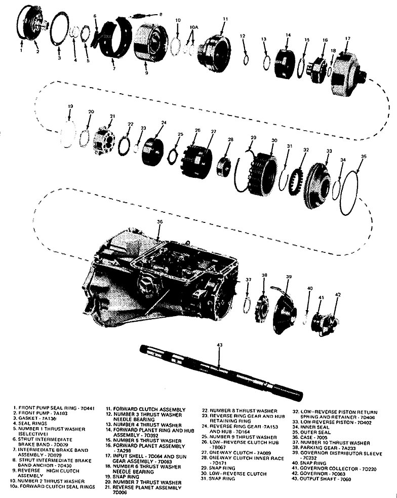
(Fig. 39) Drivetrain Disassembled
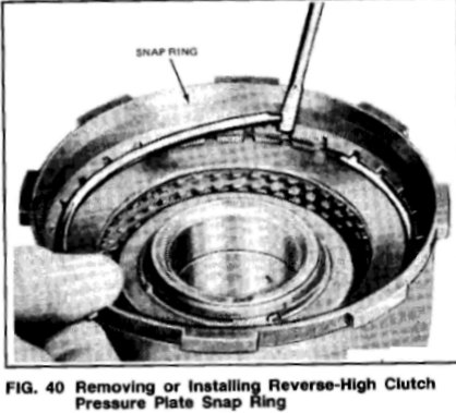
(Fig. 40)
1. Separate the drive train as shown in Fig. 39. Remove the pressure plate snap ring as shown in Fig. 40.
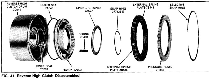
2. Remove the pressure plate and the drive and driven (internal and external spline) clutch plates (Fig. 41).
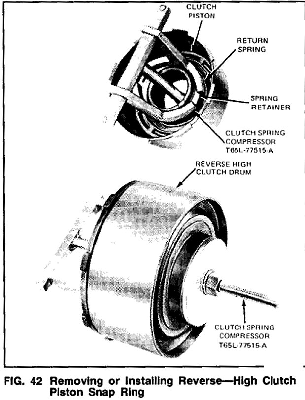
3. Install Clutch Spring Compressor, Tool T65L-77515-A (Fig. 42) on the reverse-high clutch drum. Make sure that the legs clear the snap ring enough to remove it. Remove both snap rings and remove the tool.
4. Remove the spring retainer and the piston return springs.
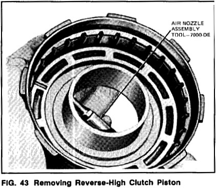
5. Apply air pressure to the piston apply hole in the clutch hub using TOOL7OOO-DE (Fig. 43) and remove the piston.
6. Remove the piston outer seal from the piston and the inner seal from the clutch drum (Fig. 41).
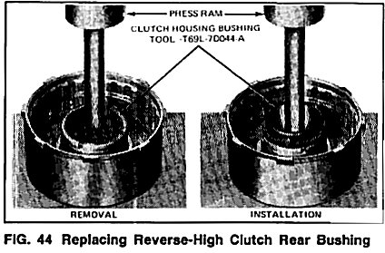
7. Remove the front and rear bushings from the clutch drum if they are worn or damaged. To remove the front bushing, use a cape chisel and cut along the bushing seam until the chisel breaks through the bushing wall. Pry the loose ends of the bushing up with an awl and remove the bushing. To remove the rear bushing, use Tool T69L-70044-A shown in Fig. 44, and press the bushing from the drum.
Assembly
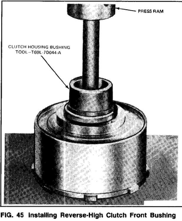
1. If the clutch drum bushings was removed, position the drum a press and press new bushings into the drum with the Tool T69L-7DO44-A shown in Figs. 44 and 45.
2. Dip the new seals in transmission fluid and install one on the drum and one on the piston.
3. Install the piston in the clutch drum.
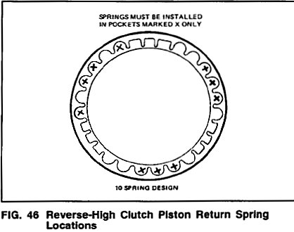
4. Position the piston return springs in the piston sockets (Fig. 46). Place the spring retainer on the springs.
5. Install Clutch Spring Compressor, Tool T65L-77515-A (Fig. 42) and compress the springs. Make certain that the spring retainer is centered while compressing the springs. Install the snap ring. Before releasing the pressure on the tool, make certain that the snap ring is positioned inside of the four snap ring guides on the spring retainer.
6. Clutch plate usage varies with each model, refer to the specification for the number of plates required.Specifications Dip the clutch plates in clean transmission fluid. Install the clutch plates alternately starting with a steel drive (internal) plate (Fig. 41). When new composition clutch plates are used, soak the plates in automatic transmission fluid, (Spec. ESP-M2C116-H) or equivalent, for 15 minutes before they are assembled.
7. After all clutch plates have been installed, position the pressure plate in the clutch drum. Install the pressure plate (selective) snap ring.
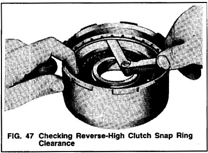
8. With a feeler gauge, check the clearance between the pressure plate and snap ring (Fig. 47).
9. The pressure plate should be held downward as the clearance is checked. The clearance should be 0.558-0.91 4mm (0.022-0.036 inch). If the clearance is not within specifications, selective thickness snap rings are available in the following thicknesses:
1.42-1.52mm (0.056-0.060 inch)
1.65-1.75mm (0.065-0.069 inch)
1.87-1.9Bmm (0.074-0.078 inch)
2.10-2.2Omm (0.083-0.087 inch)
2.33-2.43mm (0.092-0.096 inch)
2.79-2.89mm (0.110-0.114 inch)
3.25-3.35mm (0.128-0.132 inch)
Install the correct size snap ring and re-check the clearance.