Manual Shift Linkage Grommet
REMOVAL AND INSTALLATION
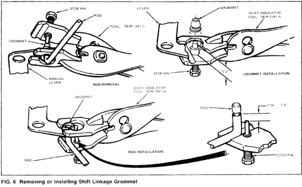
Fig. 6
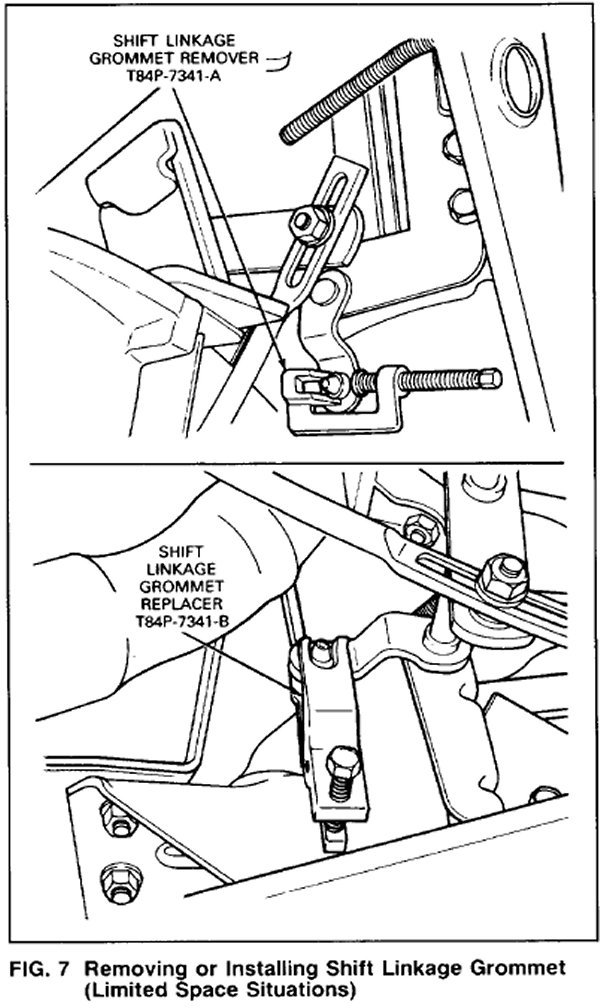
Fig. 7
Manual Shift Linkage Grommet
The automatic transmission linkage Systems make use of a polyurethane plastic grommet to connect the various rods, levers and adjusting stud. Whenever a rod is disconnected from a grommet type connector the old grommet must be removed and a new one installed. Remove and install the grommet as follows:
1. Place the lower jaw of the Shift Linkage Installation Tool, T67P-7341-A between the lever and the rod Fig 6). For areas with limited space, use Shift Linkage Grommet Remover, T84P-7341-A for removal of the grommet (Fig. 7). Position the stop pin against the end of the control rod (Fig. 6) and force the rod out of the grommet. Remove the grommet from the lever by cutting off the large shoulder with a sharp knife. The grommet must be removed from the lever and a new one installed each time the rod is disconnected.
2. Adjust the stop pin to 12.70mm (1/2 inch) and coat the outside of the grommet with Multi-Purpose Long-Life Lubricant, C1AZ-19590-B (ESAM1C75-B) or equivalent. Place a new grommet on the stop pin and force it into the lever hole. Turn the grommet several times to be sure it is properly seated.
3. Readjust the stop pin to the height shown in Fig. 6. The pin height is determined by the length of the rod end which is to be installed into the grommet. If the pin height is not adjusted, the rod may be pushed too far through the grommet causing damage to the grommet retaining lip.
NOTE: Coat ends of rods with D4AZ-19590-A, linkage lube or equivalent before installing in new grommet.
4. With the pin height properly adjusted, position the rod on the tool and force the rod into the grommet until the groove in the rod seats on the inner retaining lip of the grommet. For areas with limited space, use Shift Linkage Grommet Replacer, T84P-7341-B for grommet installation (Fig. 7).