C 6
REMOVAL AND INSTALLATION
C6 Transmission
F-150-F-250-F-35O (4x2) (4x4) and Bronco
Removal
1. Drive the vehicle on a hoist, but do not raise at this time. Disconnect neutral switch wire at the plug connector.
2. Remove the two upper converter housing-to-engine bolts.
3. Raise the vehicle on a hoist or stands.
4. Place the drain pan under the transmission fluid pan. Starting at the rear of the pan and working toward the front, loosen the attaching bolts and allow the fluid to drain. Finally remove all of the pan attaching bolts except two at the front, to allow the fluid to further drain. With fluid drained, install two bolts on the rear side of the pan to temporally hold it in place.
5. Remove the converter drain plug access cover from the lower end of the converter housing.
6 Remove the converter-to-flywheel attaching nuts. Place a wrench on the crankshaft pulley attaching bolt to turn the converter to gain access to the nuts.
7. With the wrench on the crankshaft pulley attaching bolt, turn the converter to gain access to the converter drain plug. Place a drain pan under the converter to catch the fluid and remove the plug. After the fluid has been drained, re-install the plug.
8. On (4x2) applications disconnect the driveshaft from the rear axle and slide shaft rearward from the transmission. Install a seal installation tool in the extension housing to prevent fluid leakage.
9. Disconnect the speedometer cable from the extension housing.
10. Disconnect the downshift and manual linkage rods from the levers at the transmission.
11. Disconnect the oil cooler lines from the transmission.
12. Remove the vacuum hose from the vacuum diaphragm unit Remove the vacuum line from the retaining clip.
13. Disconnect the cable from the terminal on the starter motor. Remove the three attaching bolts and remove the starter motor.
14. On F-150-F-350 (4x4) and Bronco vehicles, remove the transfer case.
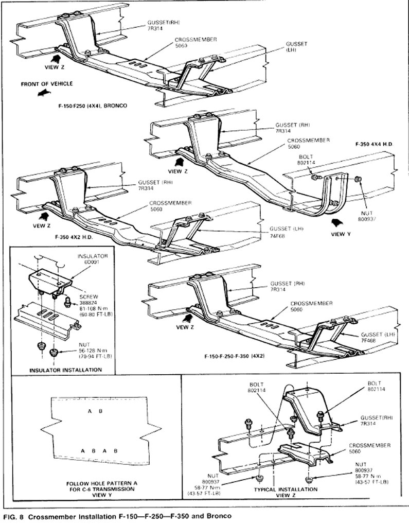
15. Remove the two engine rear support and insulator assembly-to-attaching bolts (Fig. 8).
16. Remove the two engine rear support and insulator assembly-to-extension housing attaching bolts (Fig. 8).
17. Remove the six bolts securing the No. 2 crossmember to the frame side rails (Fig. 8).
18. Raise the transmission with a transmission jack and remove the crossmember.
19. Secure the transmission to the jack with the safety chain.
20. Remove the remaining converter housing-to-engine attaching bolts.
21. Move the transmission away from the engine. Lower the jack and remove the converter and transmission assembly from under the vehicle.
Installation
1. Tighten the converter drain plug to 11-37 N.m (18-28 ft-lbs).
2. Position the converter on the transmission making sure the converter drive flats are fully engaged in the pump gear.
3. With the converter properly installed, place the transmission on the jack. Secure the transmission to the jack with the chain.
4. Rotate the converter until the studs and drain plug are in alignment with their holes in the flywheel.
5. Move the converter and transmission assembly forward into position, using care not to damage the flywheel and the converter pilot. The converter must rest squarely against the flywheel. This indicates that the converter pilot is not binding in the engine crankshaft. Do not allow converter drive flats to disengage from pump gear.
6. Install and tighten the converter housing4o-engine attaching bolts to 55-67 N.m (40-50 ft-lbs) on gasoline engines and 67-87 N.m (50-65 ft-lbs) on diesel engines.
7. Remove the transmission jack safety chain from around the transmission.
8. Position the No.2 crossmember to the frame side rails. Install and tighten the attaching bolts to specifications.
9. Install transfer case on F-150-F-250 (4x4) and Bronco.
10. Position the engine rear support and insulator assembly above the crossmember. Install the rear support and insulator assembly-to-extension housing mounting bolts and tighten the bolts to specifications.
11. Lower the transmission and remove the jack.
12. Secure the engine rear support and insulator assembly to the crossmember with the attaching bolts and tighten them to specifications.
13. Connect the vacuum line to the vacuum diaphragm making sure that the line is in the retaining clip.
14. Connect the oil cooler lines to the transmission.
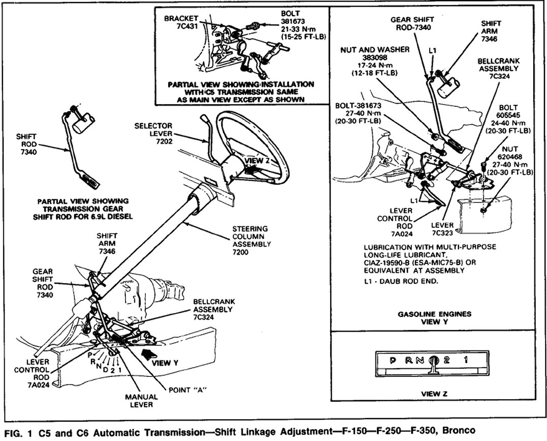
15. Connect the downshift and manual linkage rods to their respective levers on the transmission. When making transmission control attachments new retaining ring and grommet should always be used. Note precautions necessary to prevent grommet damage. Attach shift rod to the steering column shift lever. Align the flats of the adjusting stud with the flats of the rod slot and insert the stud through the rod. Assemble the adjusting stud nut and washer to a loose fit. Perform a linkage adjustment.
16. Connect the speedometer cable to the extension housing.
17. Secure the starter motor in place with the attaching bolts. Connect the cable to the terminal on the starter.
18. Install a new 0-ring on the lower end of the transmission filler tube and insert the tube in the case.
19. Secure the converter-to-flywheel attaching nuts and tighten them to 28-40 N m (20-30 ft-lbs).
20. Install the converter housing access cover and secure it with the attaching bolts.
21. Connect the driveshaft.
Shift Control Linkage
22. Adjust the shift linkage. Adjustments
23. Lower the vehicle. Then install the two upper converter housing-to-engine bolts and tighten them to 55-67 N.m (40-50 ft-lbs) on gasoline engines and 67-87 N.m (50-65 ft-lbs) on diesel engines.
24. Connect neutral switch wire to plug connector.
25. Make sure the drain pan is securely attached, and fill the transmission to the correct level with the specified fluid.