AOD
ADJUSTMENTS AUTOMATIC OVERDRIVE TRANSMISSION
Throttle Valve (TV) Control Cable Adjustment Service Adjustment Procedure
Two methods of TV system adjustment are available.
a. TV cable adjustment with engine off.
b. TV control pressure check and adjustment procedure with engine on.
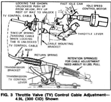
The Throttle Valve (TV) Control Gable System consists of a cable attaching stud on the carburetor or throttle body throttle lever, the TV Control Cable Assembly, the External TV Control Lever on the transmission, and the Cable Mounting Brackets at the carburetor and transmission (Fig.3) As the carburetor throttle is moved from idle to wide open throttle (WOT), the TV control cable pulls the transmission TV control lever from Idle to WOT. Return of the cable and transmission lever towards idle is accomplished by the return spring on the transmission end of the cable assembly. This spring and the end of the cable assembly is protected by a flexible rubber boot. The transmission external TV control lever actuates the internal TV control mechanism which regulates the TV control pressure. The travel of this lever is controlled by stops internal to the transmission.
The TV control cable is set and locked to its proper length during initial assembly by pushing in the locking tab at the carburetor end of the cable assembly. When the tab is unlocked, the cable is released for adjustment. The take-up spring at this end of the cable automatically tensions the cable when released. With the slack taken up and the locking tab pushed in, the take-up spring plays no part in the operation of the system.
Under normal circumstances, it should not be necessary to alter or readjust the initial setting of the TV control cable. Situations requiring readjustment of the TV control cable include maintenance involving the removal and/or replacement of the carburetor, transmission, or TV cable assembly. Readjustment of the TV control cable would also be necessary to correct complaints of poor transmission shift quality that would have been caused by an misadjustment of the TV control cable.
When the TV control cable is properly set, the transmission TV control lever will be at its internal idle stop (lever to rear as far as it will travel) when the carburetor throttle lever is at its minimum idle stop (anti-diesel stop).
TV CABLE ADJUSTMENT WITH ENGINE OFF
IDLE SPEED CONTROL MOTOR (ISC) APPLICATION
The 4.9L (300 CID) Engine is equipped with Idle Speed Control (ISC) and when the engine is shut off, the SC plunger automatically extends and moves the throttle lever to fast idle in preparation for the next time the engine is started. This engine off throttle position cannot be used for checking or adjusting the TV control cable. Refer to the following procedures for method of retracting the ISC plunger.
The 5.OL (302 CID) EFI engine is equipped with an Air By-Pass Idle Speed Control (ISC) System. Idle speed is regulated by by-passing air through the throttle body and does not affect the throttle lever position. Therefore, NO retraction of the Idle Speed Control Plunger is required before adjusting the TV Control Cable.
At WOT, the transmission TV control lever may or may not be at its WOT stop. The wide open throttle position must not be used as a reference point for adjusting the TV control cable.
IDLE SPEED AFFECT ON THE TV CONTROL CABLE
Both the 4.9L (300 CID) and the 5.OL (302 CID) EFI have an idle Speed Control (ISC). Idle speed adjustment is automatic and TV Cable adjustment will normally not be required.
The 4.9L (300 CID) engine uses a DC motor ISC that positions the throttle to automatically adjust idle speed. In some cases, a new low-mileage engine may cause the transmission to exhibit moderate symptoms of a short cable. These symptoms will fade as the engine is broken in and the ISC adjusts the idle speed.
The 5.OL (302 CID) EFI engine uses an air By-Pass ISC that does not affect throttle position. Therefore, idle automatic setting does not affect TV Cable adjustment
ADJUSTMENT PROCEDURE-ISC PLUNGER RETRACTION
NOTE: This procedure applies to the 4.9L (300 CID) only. For the 5.OL (302 CID) EFI, go directly to the TV Cable
Adjustment procedure in this Section.
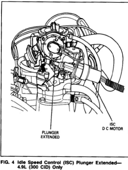
When the engine is shut off, the ISC plunger automatically extends and moves the throttle lever to fast idle in preparation for the next time the engine is started (Fig. 4). The TV cable cannot be correctly adjusted in this position.
The ISC plunger must be retracted as follows: Note the ISC plunger will retract only it the procedure is followed in the exact sequence.
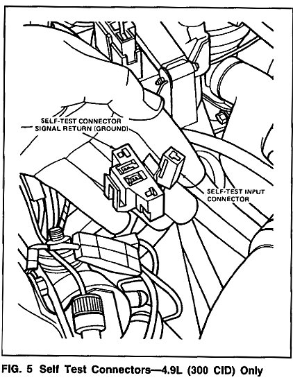
1. In the engine compartment (typically in the area of the right hand passenger side fender wall), locate the Self Test Connector and Self Test Input (STI) Connector. These two connectors are located next to each other (Fig. 5).
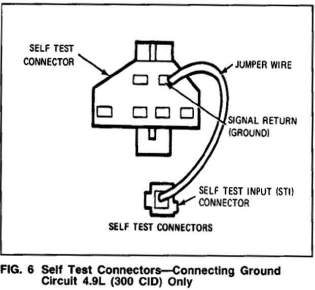
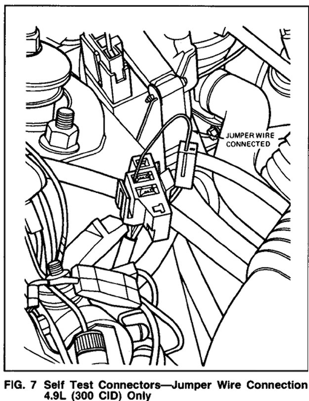
2. Connect a jumper wire between the STI connector and the Signal Return (ground) of the Self Test Connector. Refer to Figs. 6 and 7 for the correct location of the ground circuit between connectors.
3. Turn the ignition key to the Run position. Do not start engine.
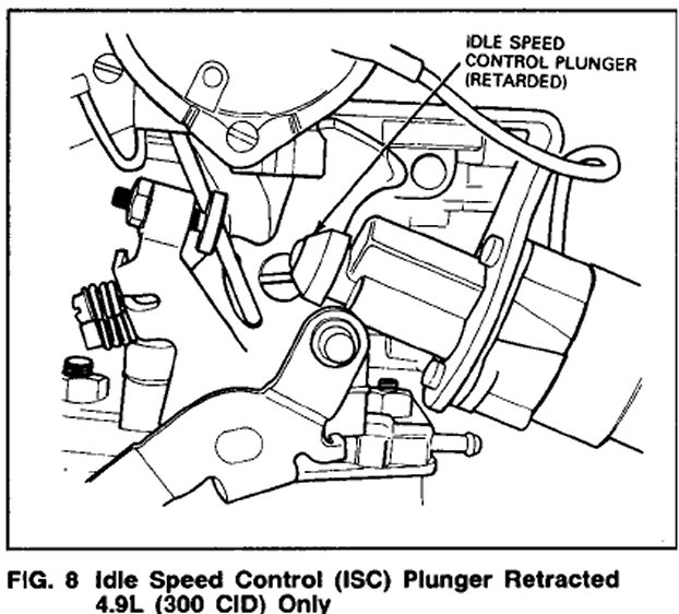
4. ISC plunger will retract. Wait until plunger is fully retracted, about 10 seconds (Fig. 8).
5. Shut On key. REMOVE JUMPER WIRE. Remove air cleaner. Proceed to the TV Cable Adjustment Procedure.
TV Cable Adjustment Procedure-Retention Spring--4.9L (300 CID) and 5.OL (302) EFI
1. Set parking brake and put selector in "N" (Do not put selector in "P").
. Remove the protective cover over the cable linkage on the 5.OL (302 CID) engine.
3. Verify that the throttle lever is at the idle stop. If it isn't, check for binding or interference in the throttle system. Do Not Attempt to Adjust Idle Stop.
4. Verify that the cable routing is tree of sharp bends or pressure points and that the cable operates freely. Lubricate the TV lever ball stud with Multi-Purpose Long-Life Lubricant, C1AZ-19590-B (ESAM1C75-B) or equivalent if necessary. Check for damage to cable or rubber boot.
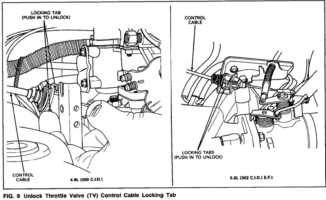
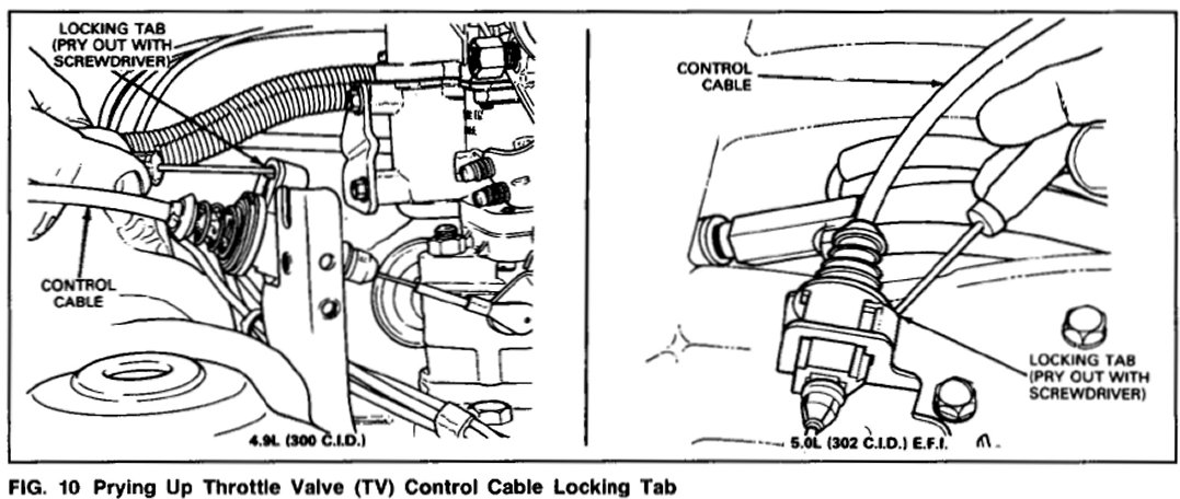
5. Unlock the locking tab at the carburetor end by pushing up from below, and prying up the rest of the way to free the cable (Figs. 9 and 10).
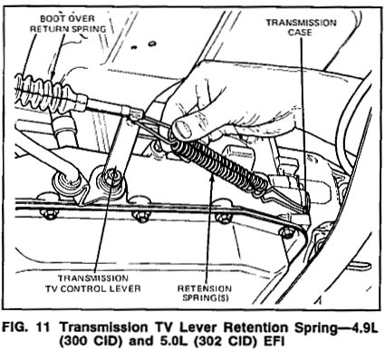
6. A retention spring must be installed on the TV control lever, to hold it in the idle position (as far to rear as the lever will travel) with about ten pounds of force. It a suitable single spring is not available, two V8 TV return springs may be used. Attach retention spring(s) to the transmission TV lever and hook rear end of spring to the transmission case (Fig. 11).
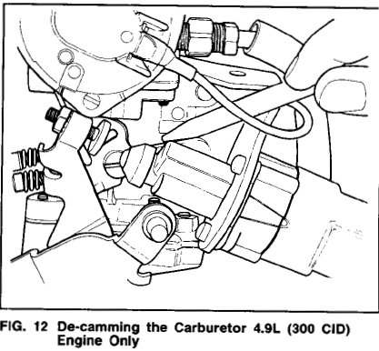
7. On 4.9L (300 CID) engines, de-cam the carburetor (Fig. 12). The carburetor throttle lever must be in the anti-diesel idle position. Verify that the take-up spring (carburetor end of cable) properly tensions the cable and that there is no binding or sticking in the sliding adjusting mechanism. If this spring is loose or bottomed out, check for bent cable brackets (Fig. 12).
NOTE: The 5.OL (302 CID) EFI engine does not have a fast idle cam.
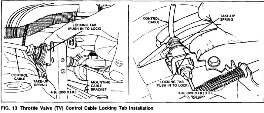
8. Push down on the locking key until flush (Fig. 13).
9. Remove the retention spring(s) from the transmission TV lever.
TV CONTROL PRESSURE CHECK AND ADJUSTMENT PROCEDURE WITH ENGINE ON
NOTE: This procedure requires the use of TV Pressure Gauge with Hose, T86L-70002-A or equivalent. The results of the adjustment procedure depends on the accuracy of the pressure gauge. A pressure gauge should be checked periodically (approximately once a year) and recalibrated twice a year or when the following occurs:
a. The needle will not return to 0 psi under no pressure.
b. The needle goes past 0 psi (negative side) under no pressure.
c. Bumping or droppinq a pressure gauge.
1. Attach TV Pressure Gauge with Hose, T86L-70002-A or equivalent to the TV port on the transmission. On some applications it might be easier to use the TV Pressure Fitting Service Tool No. D8OL-77001-A.
2. Remove the protective cover over the cable linkage on the 5.OL (302 C.I.D.) EFI Engine.
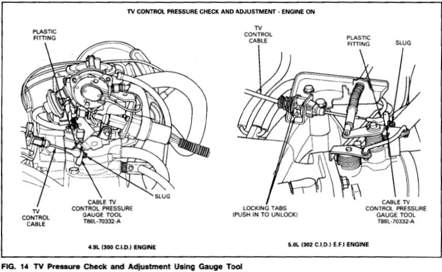
3. Insert the tapered end of the Cable TV Control Pressure Gauge Tool, T86L-70332-A between the crimped slug on the end of the cable and the plastic cable fitting that attaches to the throttle lever (Fig. 14). Push in gauge tool, forcing the crimped slug away from the plastic fitting. Make sure gauge tool is pushed in as far as it will go.
4. Operate the engine until normal operating temperature is reached. The transmission fluid temperature should be approximately 100-150° F. Do not make pressure check if transmission fluid is cold or too hot to touch.
5. Set parking brake and place shift selector in N (neutral). With gauge block in place and engine idling in neutral, the TV pressure should be 35 +/- 5 psi. For best transmission function, set the TV pressure as close as possible to 35 psi using the following procedure.
NOTE: Do not check or set TV pressure in P (Park).
6. Unlock the TV Cable Locking Tab at the carburetor (or throttle body). The adjuster preload spring should cause the adjusting slider to move away from the throttle body and the TV pressure should increase.
7. Push on the slider from behind the bracket until the TV pressure is 35 psi. While still holding the slider, push down on locking tab as far as it will go, locking slider in position.
8. Remove gauge tool, allowing cable to return to its normal idle position. With the engine still idling in neutral, TV pressure must be at or near zero (less than 5 psi). If not, reinstall gauge tool. Repeat steps 6 and 7 but set the TV pressure to a pressure less than 35 psi but not less than 30 psi. Remove gauge tool and recheck TV pressure to determine if it is at or near zero.