Control Pressure Test/Shift Point Checks
Control Pressure Test
AOD
Line pressure and throttle pressure on the Automatic Overdrive Transmission is tested in the idle position (zero T.V.) and wide-open-throttle position. Line pressure and throttle pressure specifications can be found in the Technical Service Bulletin-Special Specifications Issue. In each of the two modes the Reverse specifications will be higher than the others.
1. Be sure the T.V. linkage is properly adjusted.
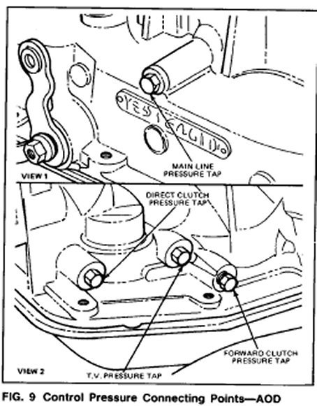
2. Connect a 300 psi gauge to the line pressure port on the case left side lust above the control lever (Fig. 9). Have sufficient flexible hose to make the gauge accessible while operating the engine.
3. Connect a 0-100 psi pressure gauge to the TV port on the right side of the case (see Fig. 9). Have sufficient flexible Hose to make the gauge accessible while operating the engine.
CAUTION: Pressure gauges affect the shift quality of the transmission. Care should be taken NOT to accelerate or decelerate rapidly. Possible transmission failure could result
NOTE: W.O.T. readings are to be made at full stall. However, be sure to run the engine at fast idle in neutral for cooling between test.
4. Run the engine until it is hot.
CAUTION: Idle pressure must be read with the throttle off the fast idle cam.
5. Apply the service and parking brakes firmly and shift through all the ranges. Record the line pressure and the throttle pressure and compare it with specifications.
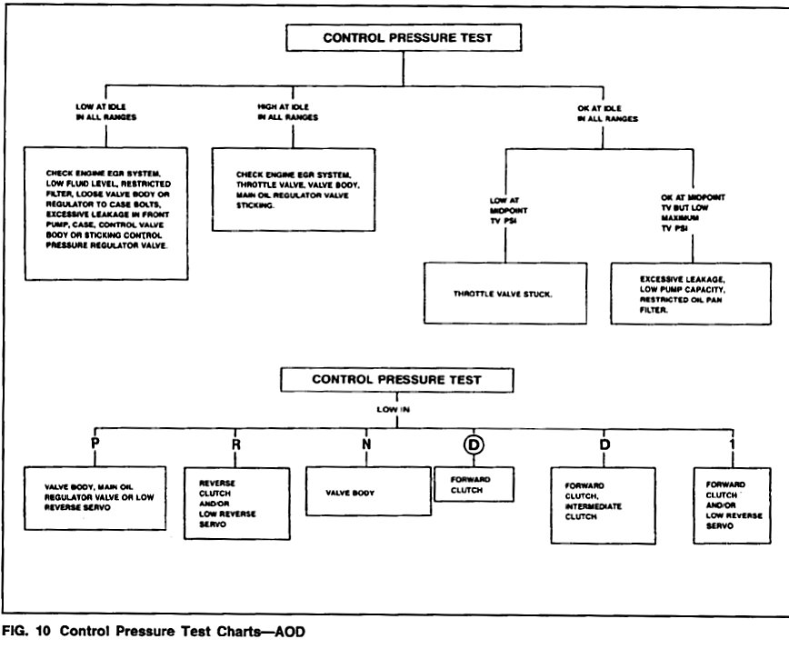
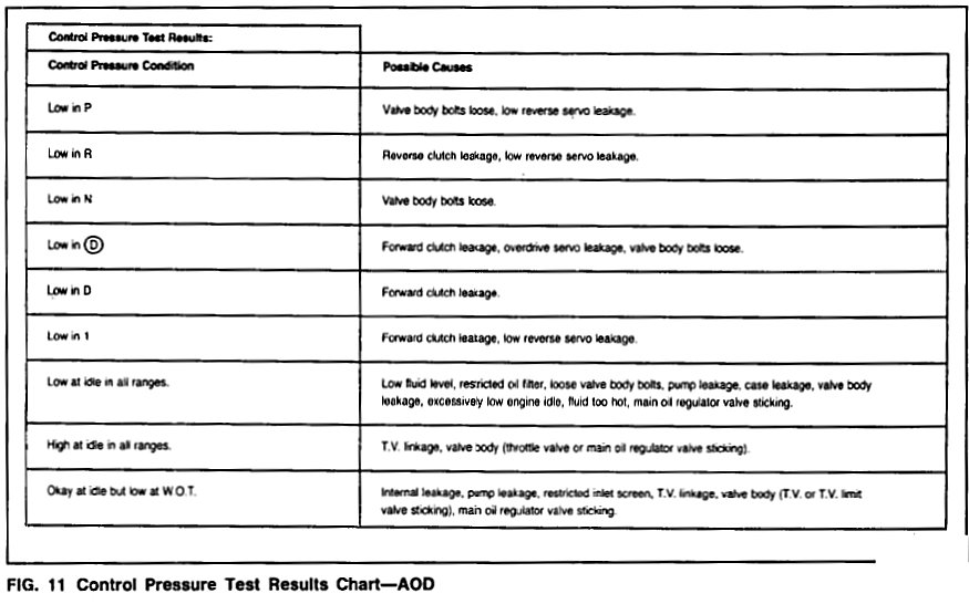
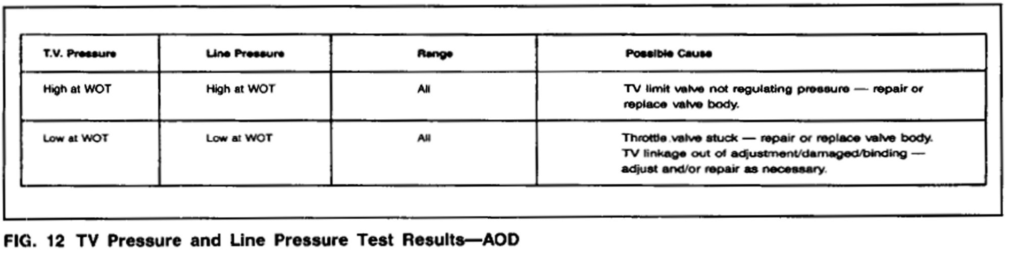
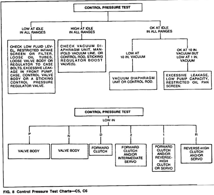
After making the control pressure tests, analyze the results to relate to the conditions in Figs. 10, 11 and 12.
Keep in mind that clutch and servo leakage may or may not show up on the control pressure test. This is because (1) the pump has a high output volume and the leak may not be severe enough to cause a pressure drop; and (2) orifices between the pump and pressure chamber may maintain pressure at the source, even with a leak downstream. Pressure loss caused by a less-than-major leak is more likely to show up at idle than at W.O.T. where the pump is delivering full volume.
Conversely, if you are manipulating the T.V. linkage to simulate W.O.T., but actually testing at idle, the leak is more likely to cause a pressure loss in the W.O.T. position.
To further isolate leakage in a clutch or servo circuit, it is necessary to remove the oil pan and valve body, and to perform case air pressure tests.
DIRECT CLUTCH PRESSURE TEST-AOD)
The direct clutch pressure test outlined below will diagnose a low pressure condition or leakage in the direct clutch circuit. A difference of 15 psi or more between direct clutch pressure and line pressure (read at the forward clutch pressure tap) will prevent a 3-4 shift.
1. Attach 0-300 psi pressure gages to the forward clutch pressure tap and to the direct clutch pressure tap (Fig. 9). Gauge accuracy must be capable of distinguishing a 15 psi difference. (If this test is done in conjunction with a control pressure test, pressure gages will be attached to all pressure taps.) Have sufficient flexible hose to read the gages in the vehicle.
CAUTION: Pressure gauges affect the shift quality of the transmission. Care should be taken not to accelerate or decelerate rapidly. Possible transmission failure could result.
2. Drive the vehicle. When pressure is applied to the direct clutch, note the difference between the line pressure read at forward clutch pressure tap and the direct clutch pressure.
3. If the difference in pressures is less than 15 psi, the direct clutch circuit is Ok.
4. If the difference is greater than 15 psi, there could be a leak in the direct clutch pressure circuit. If the difference does exceed 15 psi, the gauges on line pressure and direct clutch pressure can be switched to confirm that gage calibration difference is not the cause.
Stall Test
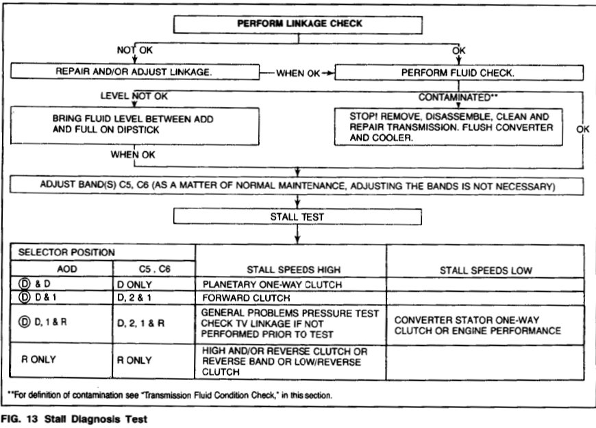
Refer to Fig. 13.
The stall test checks converter clutch operation and installation, the holding ability of the forward clutch, reverse clutch, the low-reverse bands, the planetary one-way clutch and engine performance.
The test should be done only with the engine coolant and transmission fluid at proper levels and at operating temperature, and with the TV linkage set properly.
Apply the service and parking brakes firmly for each stall test.
1. Find the specified stall RPM for the vehicle by refering to the Technical Service Bulletin-Special Specifications Issue. Use a grease pencil to mark the RPM on the dial of a tachometer.
2. Connect the tachometer to the engine
3. In each of the following ranges for Automatic Overdrive (D), D, 1, R; for C6, C5-D, 2, 1, R; press the accelerator to the floor and hold it just long enough to let the engine get to full RPM. While making this test, do not hold the throttle open for more than five seconds at a time.
4. Note the results in each range
5. After each range, move the selector lever to N (neutral) and run the engine at 1000 RPM for about 15 seconds to cool the converter before making the next test.
6. Refer to Fig. 13 for corrective actions.
IMPORTANT:If the engine speed recorded by the tachometer exceeds the maximum limits given in the Specifications, release the accelerator immediately because clutch or band slippage is indicated.
Governor Check C5 and C6
The governor can be checked at the same time as the Control Pressure Test is performed and in the same manner.
Raise the vehicle with an axle or frame hoist so that the rear wheels are clear of the floor. Disconnect and plug the vacuum line to the vacuum diaphragm unit. Connect the line from the distributor tester if available to the vacuum diaphragm unit. Vacuum pump can be used with an extended vacuum hose to operate from within the vehicle.
CAUTION: Never exceed 96 km (60 mph) speedometer speed.
Place the transmission in D (DRIVE), no load on the engine and apply 10 inches of vacuum to the vacuum diaphragm unit. Increase the speed slowly and watch the speedometer. Check the mph at which the control pressure cutback occurs. It should occur between 16-32 km (10-20 mph).
NOTE: After each test, move the selector to N (neutral) and run the engine at 1000 RPM to cool the transmission.
The governor is good it the cutback occurs within these specifications. If the cutback does not occur within specifications, check shift speeds to verify that it is the governor and not a stuck cutback valve, then repair or replace the governor.
AOD
Perform a shift point check. (Road test or in shop). It the shift points are not within specifications, proceed with the following governor check. Accelerate vehicle to 40 km/h (25 mph) then back off throttle completely. The transmission should shift to third gear.
Shift Point Checks
Road Test C5 and C6
This check will determine if the governor pressure and shift control valves are functioning properly.
Check the minimum throttle upshifts in D (DRIVE). The transmission should start in first gear, shift to second, and then shift to third, within the shift points listed in Technical Service Bulletin-Special Specifications Issue.
With the transmission in third gear, depress the accelerator pedal through the detent (to the floor). The transmission should shift from third to second or third to first, depending on the vehicle speed.
Check the closed throttle downshift from third to first by coasting down from about 48 km (30 mph) in third gear. The shift should occur within the limits listed in the Specifications.
When the selector lever is at 2 (SECOND), the transmission can operate only in second gear.
With the transmission in third gear and road speed over 80 km (50 mph) the transmission should shift to second gear when the selector lever is moved from D (DRIVE) to 2 (SECOND) or 1 (FIRST).
The transmission will downshift from second or third to first gear when this same manual shift is made below approximately 40 km (25 mph) with a C5 transmission, 48 km (30 mph) with a C6 transmission.
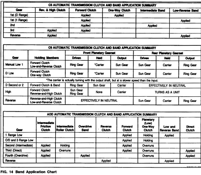
Refer to the band application chart in Fig. 14 to aid in diagnosis of transmission conditions.
In Shop
A shift test can be performed in the shop to check shift valve operation, governor circuits, shift delay pressures, throttle boost and downshift valve action.
Raise the vehicle with an axle or frame hoist so that the rear wheels are clear of the floor. Disconnect and plug the vacuum line to the vacuum diaphragm unit (C5 and C6). Connect the line from the distributor tester vacuum pump to the vacuum diaphragm unit.
CAUTION: Never exceed 96 km (60 mph) speedometer speed.
1. To check the shift valves and governor circuits, apply 18 inches of vacuum to the transmission vacuum diaphragm unit. Place the transmission in Drive and make a minimum throttle 1-2 and 2-3 shift. At the shift points you will see the speedometer needle make a momentary surge and feel the driveline bump. If the shift points are within specification, the 1-2 and 2-3 shift valves and governor are OK. If the shift points are not within specification, perform a Governor Check to isolate the problem.
NOTE: After each test, move the selector lever to Neutral, run the engine at 1000 rpm to cool the transmission.
2. To check the shift delay pressures and throttle boost, decrease the vacuum at the vacuum diaphragm to 0-2 inches. Make a 1-2 shift test. If the shift point raises to specification, the throttle boost and shift delay systems are functioning.
3. To check downshift valve action. Leave the vacuum to the vacuum diaphragm at 0-2 inches. Position the downshift linkage in the wide open throttle position (through the detent) and repeat the 1-2 shift test. The speed at the shift point should be higher.
Shift speed specifications can be found in the Technical Service Bulletin-Special Specifications Issue.
Shift Point Checks AOD Road Test
This check will determine if the governor pressure and shift control valves are functioning properly. During the shift point check operation, if the transmission does not shift within specifications or certain gear ratios cannot be obtained, refer to the diagnosis wheel or to the symptom analysis section to resolve the problem. Symptom Related Diagnostic Procedures
Shift speed specifications can be found in the Technical Service Bulletin-Special Specifications Issue.
Choke on will effect shift points minimum throttle upshifts. Check minimum throttle upshifts in the fourth gear (overdrive). The transmission should start in first gear, shift to second gear then shift to third gear and finally shift to fourth gear, within the shift points specified in the shift speed specifications.
Forced Downshifts
With the transmission in fourth gear (overdrive) depress the accelerator pedal to the floor. The transmission should downshift to third gear or to second gear, depending on vehicle road speed. Refer to the appropriate shift speed specifications.
Closed Throttle Downshifts
Closed throttle downshifts should be extremely difficult to detect. It may be necessary to attach pressure gauges to the forward and direct clutch pressure taps (Fig. 9) in order to detect 4-3 and 3-2 coast downshifts.
With gauges attached a 4-3 coast (closed throttle) downshift is signified by the application of the forward clutch (the psi reading from the gauge on the forward clutch pressure tap will indicate an increase in pressure from 0 psi to 60 psi). A 3-2 coast downshift is signified by the release of the direct clutch (the psi reading from the gauge on the direct clutch pressure tap will indicate a decrease in pressure from 60 psi to 0 psi). A 2-1 coast downshift should be imperceptible. The coast downshifts should occur within the limits set forth in the shift speed specifications.
When the shift selector is in manual low (1) the transmission will not upshift from first gear.
When the shift selector is moved from either OD (overdrive) or direct drive (D) ranges to the manual low (1) position, the transmission will downshift into second gear if the vehicle is moving over (approximately) 41 km/h (25 mph) and into first gear if the vehicle is moving less than (approximately) 41 km/h (25 MPH).
The overdrive band is applied when the transmission is in manual second. The low-reverse band is applied when the transmission is in manual first gear.
The automatic overdrive transmission will not shift into fourth gear (overdrive) at wide open throttle.
The Automatic Overdrive Transmission will not make a 4-1 downshift.
When the vehicle road speed drops below approximately 58 km/h (35 mph), the transmission automatically downshifts from (D) (overdrive) into third gear.
Shift Point Checks In Shop AOD
A shift test can be performed in the shop to check shift valve operation, governor circuits, shift delay pressures, throttle boost and downshift valve action.
Raise the vehicle with an axle or frame hoist so that the rear wheels are clear of the floor.
CAUTION: Never exceed 96 km/h (60mph) speedometer speed or rapidly apply the brakes to stop the rear wheels.
To check the shift valves and governor circuits, place the transmission in overdrive and make a minimum throttle 1-2, 2-3 and 3-4 shift test. When the shift occurs you will see the speedometer needle make a momentary surge and feel the driveline bump. If the shift points are within specification, the 1-2, 2-3 and 3-4 shift valves and governor are OK.
If the shift points are not within specification, perform a Governor Check to isolate the problem.
Place the transmission in manual 2, no load on the engine and apply 10 inches of vacuum to the vacuum diaphragm unit. Increase the speed slowly and watch the speedometer. Check the mph at which the control pressure cutback occurs. it should occur between 16-32 km (10-20 mph).
NOTE: After each test, move the selector lever to N (Neutral) and run the engine at 1000 rpm to cool the transmission.
Decrease the vacuum at the vacuum diaphragm to 0.2 inches. Repeat the check. Control pressure cutback should occur between 48-80 km (30-50 mph).
The governor is good if the cutback occurs within these specifications. If the cutback does not occur within specifications, check shift speeds to verify that it is the governor and not a stuck cutback valve, then repair or replace the governor.
Shift speed specifications can be found in the Technical Service Bulletin-Special Specifications Issue.
Diagnosis Tips AOD Only
Some tips on diagnosing problems with specific components are:
INTERMEDIATE CLUTCH OR ONE-WAY CLUTCH-transmission shuts 1-3 or slips in second gear.
REVERSE CLUTCH-slip or no engagement in R. (Also can be caused by the low-reverse band or servo.)
FORWARD CLUTCH/PLANETARY LOW ONE-WAY CLUTCH-no engagement in forward ranges or slip in forward.
OVERDRIVE BAND OR SERVO-no fourth gear, slip in fourth gear, or no engine braking in second gear in range 1.
DIRECT CLUTCH-slip in third or fourth, or no upshift beyond second.
LOW-REVERSE BAND OR SERVO-no reverse or slip in reverse. Possibly no engine braking in manual low first gear, which would isolate the problem to the band rather than reverse clutch.
Accumulators
Leaking seals on the accumulator pistons can cause their respective clutches to slip. If the 2-3 accumulator seals leak, the symptoms could resemble a direct clutch or forward clutch problem. A leaking 3-4 accumulator will cause a harsh 3-4 upshift.
T.V. Pressure Low
Another reminder: if the Shifts seem soft or mushy, do not make any heavy throttle tests. Check and adjust the T.V. linkage before making a complete road test.
Air Pressure Checks C5 and C6
A NO DRIVE condition can exist, even with correct transmission fluid pressure, because of inoperative clutches or bands. On automatic transmissions, an erratic shift can be caused by a stuck governor valve. The inoperative units can be located through a series of checks by substituting air pressure for fluid pressure to determine the location of the malfunction.
When the selector lever is at 2 (second) a NO DRIVE condition may be caused by an inoperative forward clutch. A NO DRIVE condition at D (drive) may be caused by an inoperative forward clutch or one-way clutch. When there is no drive in 1 (low) the difficulty could be caused by improper functioning of the forward clutch or simultaneous malfunction of the low-reverse band and the one-way clutch. Failure to drive in R (Reverse) could be caused by a malfunction of the reverse-high clutch or low-reverse band or clutch.
When you have a slip problem but don't know whether it is in the valve body or in the hydraulic system beyond the valve body, the air pressure tests can be very valuable.
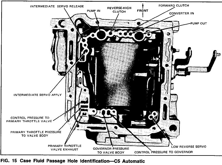
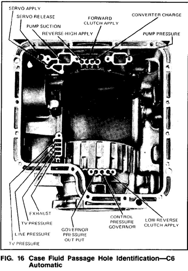
To make the air pressure checks, loosen the oil pan bolts and lower one edge to drain the transmission fluid. Remove the oil pan and the control valve body assembly. The inoperative clutches or bands can be located by introducing air pressure into the various transmission case passages (Figs. 15 and 16).
Forward Clutch
Apply air pressure to the transmission case forward clutch passages (Figs. 15 and 16). A dull thud can be heard when the clutch piston is applied. If no noise is heard, place the finger tips on the input shell and again apply air pressure to the forward or front clutch passage. Movement of the piston can be felt as the clutch is applied.
Governor
Apply air pressure to the control pressure to governor passage (Figs. 15 and 16) and listen for a sharp clicking or whistling noise. The noise indicates governor valve movement.
Reverse-High Clutch
Apply air pressure to the reverse-high clutch (Figs. 15 and 16). A dull thud indicates that the reverse-high or rear clutch piston has moved to the applied position. If no noise is heard, place the finger tips on the clutch drum and again apply air pressure to detect movement of the piston.
Intermediate Servo
Hold the air nozzle in the front servo apply tube or the intermediate servo apply passages (Figs. 15 and 16). Operation of the servo is indicated by a tightening of the front or intermediate band around the drum on C5 and C6 transmissions. Continue to apply air pressure to the servo apply tube or passage, and introduce air pressure into the front release tube or the intermediate servo release passage. The front or intermediate servo should release the band against the apply pressure.
Low-Reverse Servo Only
Apply air pressure to the low-reverse servo (Figs. 15 and 16). On C5 and AOD, the low-reverse band should tighten around the drum if the servo is operating properly.
If the servos do not operate, disassemble, clean, and inspect them to locate the source of the trouble.
If air pressure applied to either of the clutch passages fails to operate a clutch or operates both clutches at once, remove, and with air pressure, check the fluid passages in the case and front pump to detect obstructions.
Low-Reverse Clutch C6 Only
Apply air pressure to the low-reverse clutch apply passage (Fig. 16). A dull thud should be heard if the clutch is operating properly. If the passages are clear, remove the clutch assemblies, and clean and inspect the malfunctioning clutch to locate the trouble.
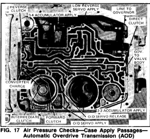
Air Pressure Checks AOD
A NO DRIVE condition can exist even with the correct transmission fluid pressure because of inoperative clutches or bands. The inoperative units can be located by substituting air pressure for fluid pressure through a series of passages to determine the location of the malfunction (Fig. 17).
A NO DRIVE condition in OD (overdrive) may be caused by an inoperative forward clutch or one-way clutch. When there is a NO DRIVE in 1st. (first), the difficulty could be caused by improper functioning of the forward clutch or low-reverse band and the one-way clutch.
Air pressure checks can also isolate slip problems as to whether the source of the problem is in the valve body or in the hydraulic system beyond the valve body.
The passages can be tested adequately with air pressure regulated at 40 psi. However, it may be necessary to use higher air pressure (90 psi) if there is difficulty in hearing the clutches apply.
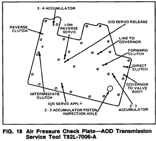
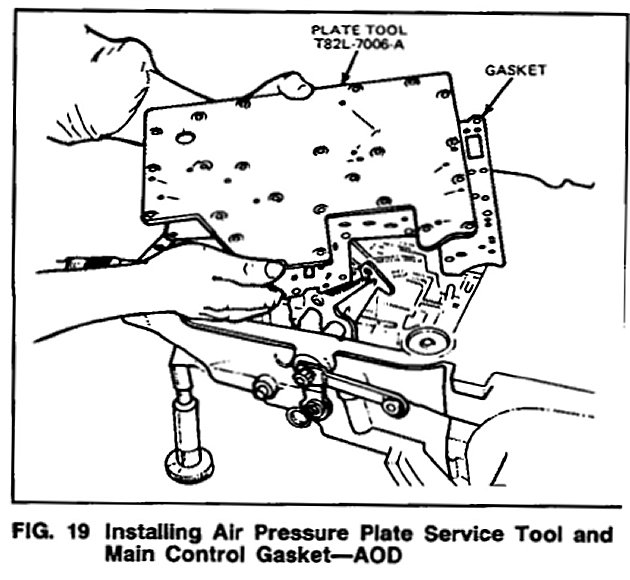
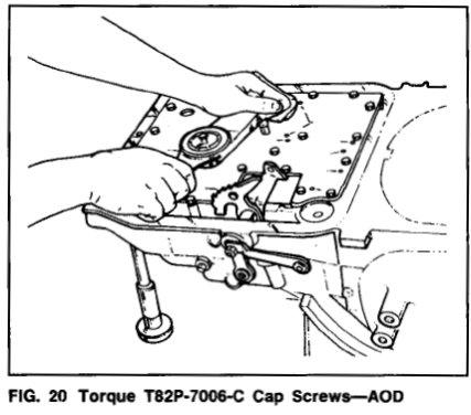
Use the main control gasket and service Tool T82L- 7006-A with T82P-7006-C cap screws (M6 x 16) to seal the case apply passages (Figs. 18 and 19). Tighten the cap screws 9-11 N.m (80-100 in. lb.) (Fig. 20). Apply air to the apply passages in the service tool plate using the air nozzle service tool Tool-7000-DE with the rubber tip Tool-7000-DD or equivalent.
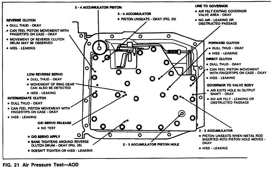
All locations of the case apply passages are stamped on the service tool plate. The transmission case apply holes are illustrated in Fig 21.
Notes on Air Checks:
If the servos or the accumulators do not operate disassemble, clean and inspect them to locate the source of the trouble. If air pressure applied to either of the clutch passages fails to operate a clutch or operates both clutches at once, remove and with air pressure, check the fluid passages in the case and front pump to detect obstructions.
Clutches-Reverse Clutch, Forward Clutch, Intermediate Clutch and Direct Clutch
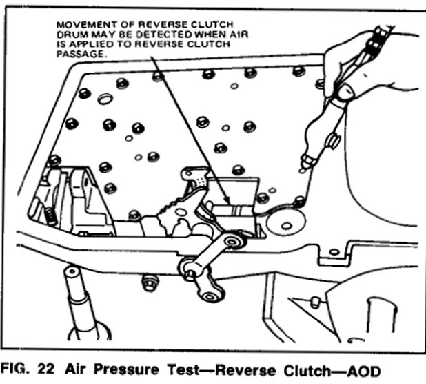
Apply air pressure to the appropriate passage in the service tool (Fig. 18). A dull thud can be heard or felt on the case as the clutch piston is applied (Fig. 21). Movement of the reverse clutch drum may also be detected when the reverse clutch passage is pressure tested (Fig. 22).
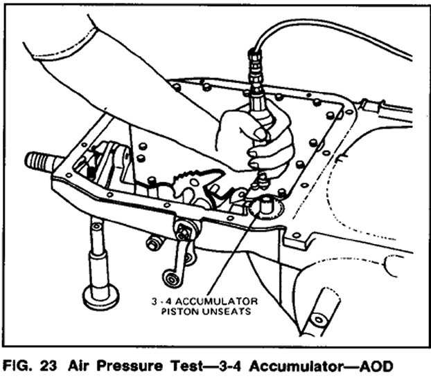
3-4 Accumulator
Apply air pressure to the 3-4 accumulator apply passage. The accumulator piston should unseat (Fig. 23).
2-3 Accumulator
Apply air pressure to the 3-4 accumulator apply passage. The accumulator piston should unseat (Fig. 23).
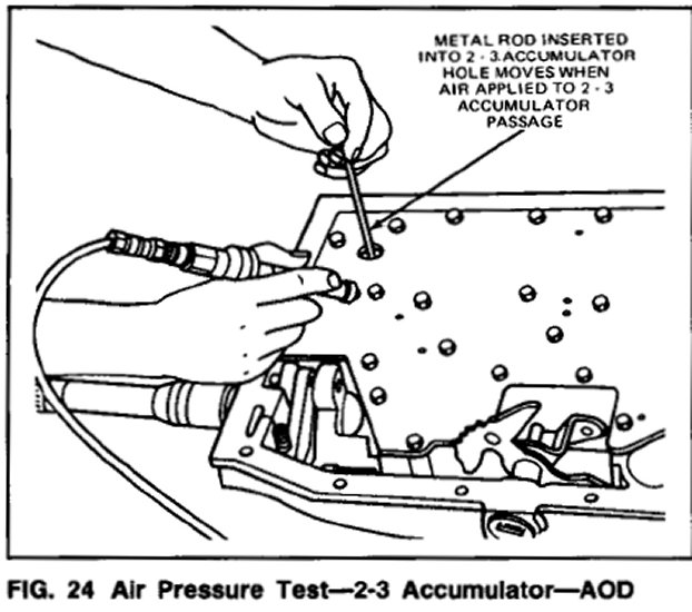
2-3 Accumulator
Apply air pressure to the 2-3 accumulator apply passage. The accumulator piston should unseat. This can be detected by inserting a metal rod into the 2-3 piston hole. When the piston unseats the rod will move. Also, a thud can be heard when the piston applies (Fig. 24).
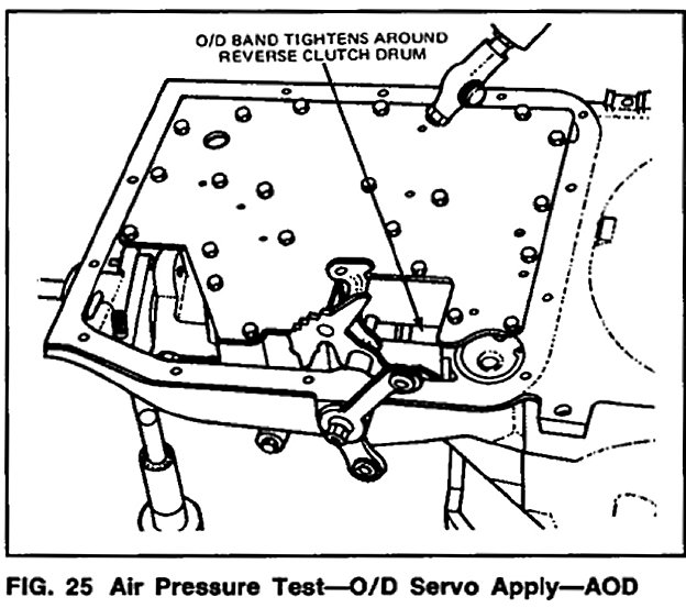
Overdrive Servo
Apply air pressure to the overdrive O/D servo apply passage in the service tool plate. Operation of the band is indicated by the tightening of the band around the reverse clutch drum (Fig. 25). The O/D servo will return to the release position as a result of spring force from the release spring. Also, when the servo returns to the release position, a thud can be felt on the O/D servo cover. The band will then relax.
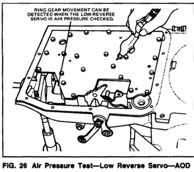
Low-Reverse Servo
Apply air pressure to the low-reverse servo apply passage in the service tool plate. A dull thud can be heard when the low-reverse band tightens around the planetary assembly drum surface. Also, movement of the ring gear can be detected (Fig. 26).
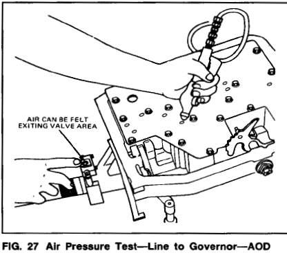
Governor
Apply air pressure to the line to governor passage while holding finger near the governor valve (Fig. 27). If air is felt exiting the valve area, the passage is unobstructed.
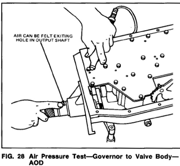
To Air pressure check the governor to valve body passage, remove the governor. Apply air pressure to the passage while holding finger over holes in the output shaft (Fig. 28). If air exists in one of the holes, the passage is unobstructed.