Clutches-Reverse Clutch, Forward Clutch, Intermediate Clutch and Direct Clutch
Clutches-Reverse Clutch, Forward Clutch, Intermediate Clutch and Direct Clutch
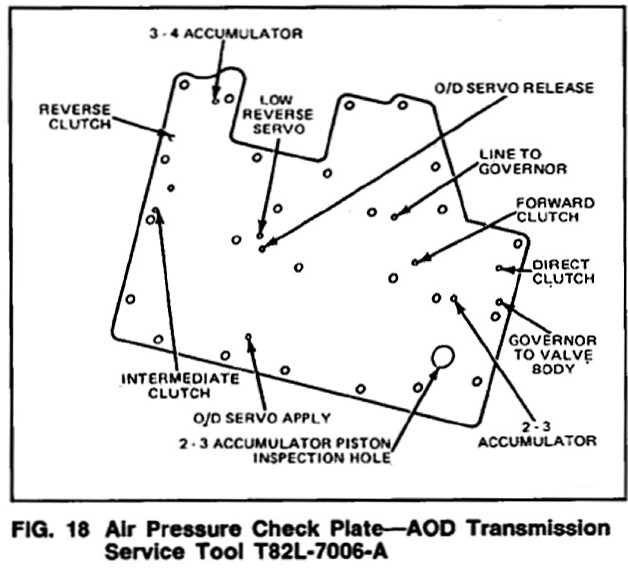
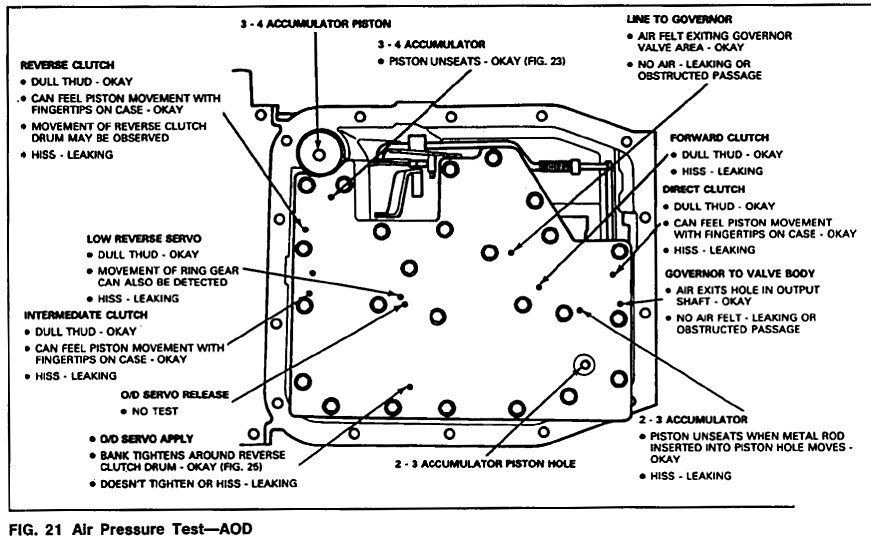
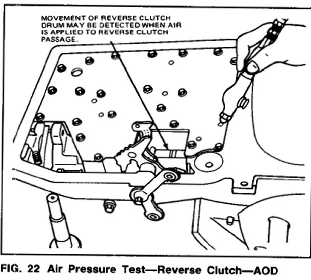
Apply air pressure to the appropriate passage in the service tool (Fig. 18). A dull thud can be heard or felt on the case as the clutch piston is applied (Fig. 21). Movement of the reverse clutch drum may also be detected when the reverse clutch passage is pressure tested (Fig. 22).
3-4 Accumulator
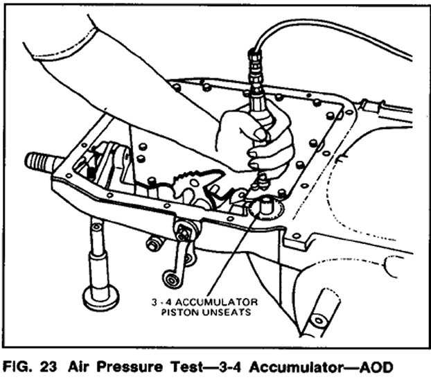
Apply air pressure to the 3-4 accumulator apply passage. The accumulator piston should unseat (Fig. 23).
2-3 Accumulator
Apply air pressure to the 3-4 accumulator apply passage. The accumulator piston should unseat (Fig. 23).
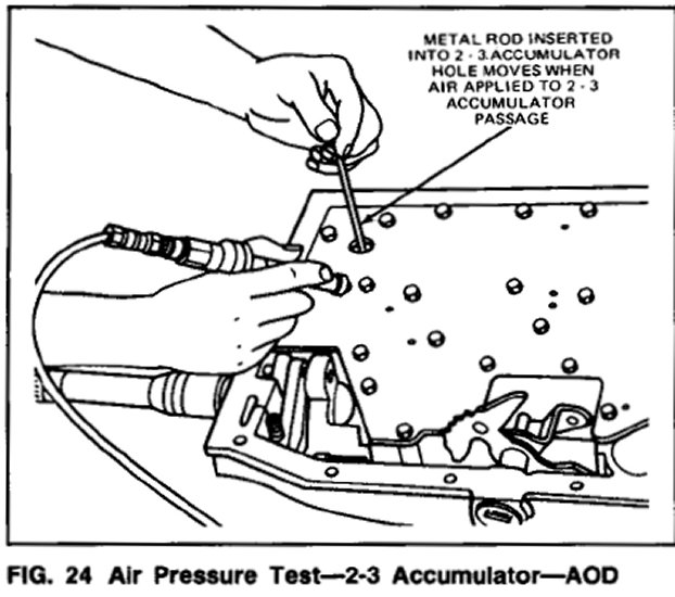
2-3 Accumulator
Apply air pressure to the 2-3 accumulator apply passage. The accumulator piston should unseat. This can be detected by inserting a metal rod into the 2-3 piston hole. When the piston unseats the rod will move. Also, a thud can be heard when the piston applies (Fig. 24).
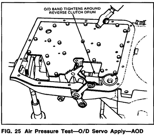
Overdrive Servo
Apply air pressure to the overdrive O/D servo apply passage in the service tool plate. Operation of the band is indicated by the tightening of the band around the reverse clutch drum (Fig. 25). The O/D servo will return to the release position as a result of spring force from the release spring. Also, when the servo returns to the release position, a thud can be felt on the O/D servo cover. The band will then relax.
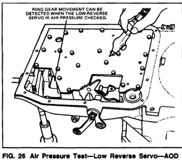
Low-Reverse Servo
Apply air pressure to the low-reverse servo apply passage in the service tool plate. A dull thud can be heard when the low-reverse band tightens around the planetary assembly drum surface. Also, movement of the ring gear can be detected (Fig. 26).
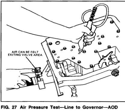
Governor
Apply air pressure to the line to governor passage while holding finger near the governor valve (Fig. 27). If air is felt exiting the valve area, the passage is unobstructed.
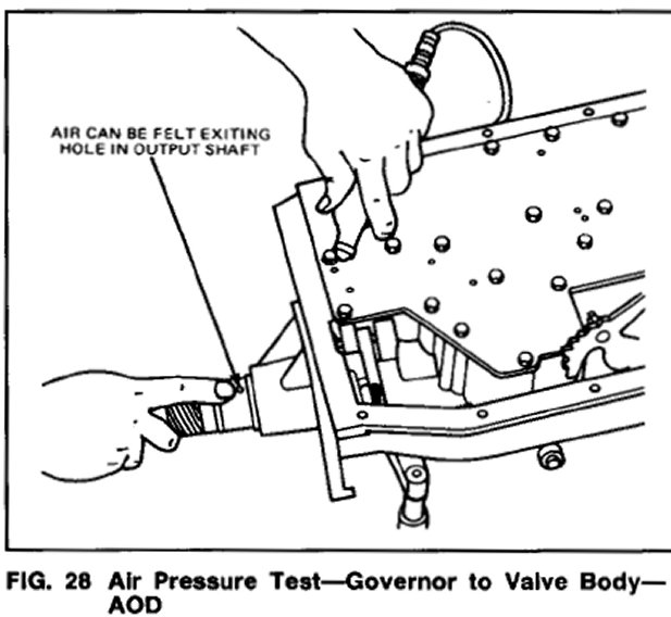
To Air pressure check the governor to valve body passage, remove the governor. Apply air pressure to the passage while holding finger over holes in the output shaft (Fig. 28). If air exists in one of the holes, the passage is unobstructed.