Control Pressure Test
Control Pressure Test C5 and C6
There are two methods of performing the control pressure test. One is to perform the test using the engine vacuum. The second method is to use a remote vacuum source such as the one provided in the distributor tester or a hand operated vacuum pump.
Engine Vacuum Pressure
When the vacuum diaphragm unit is operating properly and the manual and downshift linkage is adjusted properly, all the transmission shifts (automatic and kickdown) should occur within the road speed limits listed in the Technical Service Bulletin-Special Specifications Issue.
If the shifts do not occur within limits, or the transmission slips during shift point, use the following procedure to determine whether the engine, transmission, linkage, vacuum diaphragm unit or valve body is causing the condition. For 6.9L Diesel C6 application, see Vacuum Regulator Valve below.
Vacuum Regulator Valve (VRV) 6.9L Diesel C6
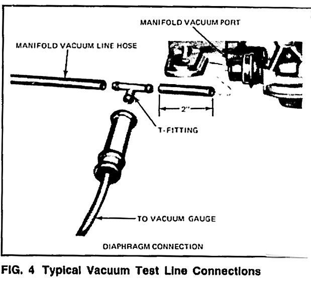
Refer to Fig 4
The Vacuum Regulator Valve (VRV) is used on E-25O-E350 and F25O-F-35O vehicles equipped with 6.9L diesel engines.
On 6.9L diesel engine trucks equipped with a C-6 automatic transmission a Vacuum Regulator Valve (VRV) is incorporated to provide a vacuum signal which is proportional to the throttle position to the vacuum diaphragm of the transmission. The VRV is necessary to provide a vacuum signal to the C-6 transmission because the diesel engine has no vacuum. The VRV is bolted to the fuel injection pump and is actuated by the throttle lever.
A constant vacuum source is supplied to the VRV by an engine driven vacuum pump which also delivers vacuum to other accessories. The VRV regulates an output vacuum signal to the transmission's vacuum diaphragm which is proportional to the throttle position. As the throttle is opened, the regulated vacuum from the VRV drops.
Should a malfunction occur in the VRV, the valve will cause a 0 vacuum signal to be sent to the diaphragm which will cause delayed and harsh-shifts to occur.
1. Attach a tachometer to the engine and a vacuum gauge to the transmission vacuum line at the manifold vacuum port (Fig. 4).
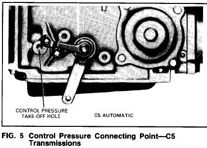
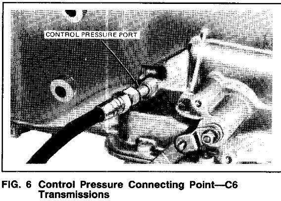
2. Attach a pressure gauge to the control pressure outlet at the transmission (Figs. 5 and 6).
CAUTION: Pressure gauges affect the shift quality of the transmission. Care should be taken NOT to accelerate or decelerate rapidly. Possible transmission failure could result.
3. Firmly apply the parking brake and start the engine.
4. Adjust the engine idle speed to the specified rpm, using the carburetor idle adjustment screw. If the engine idle speed cannot be brought within limits, check the throttle and downshift linkage for a binding condition. If linkage is satisfactory, check for vacuum leaks in the transmission diaphragm unit (Fig. 7) and its connecting tubes and hoses. Check all other vacuum operated units (such as the power brake) for vacuum leaks. Power Brake Assist
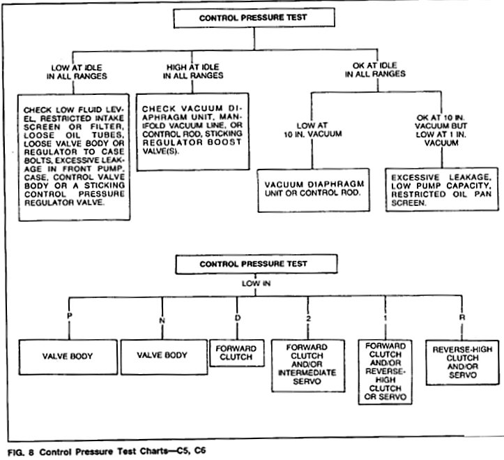
Check all other vacuum operated units (such as the power brake) for vacuum leaks. Refer to the two control pressure diagnostic guides in Fig. 8 to show what components are inoperative when the control pressure test is not within specifications. Do not proceed with the main diagnosis guide until you have made any repairs, as required, and the control pressure is within specifications as listed in the Technical Service Bulletin-Special Specifications Issue.
Vacuum Pump Method C5 AND C6
Disconnect and temporarily plug the vacuum line at the vacuum diaphragm unit. Attach a vacuum pump to the vacuum diaphragm. Apply both the parking and service brakes. Start the engine and vacuum pump. Set the vacuum at 15 inches, read and record the control pressure in all selector positions. Run the engine up to 1000 rpm, and reduce the vacuum to 10 inches. Read and record the control pressure in D, 2 and 1. Keep the engine rpm at 1000 and reduce the vacuum to 1 inch. Read and record the control pressure in D, 1, 2 and R. Refer to the two control pressure diagnostic guides in Fig. 8 to show what components are inoperative when the control pressure test is not within specifications. Do not proceed with the main diagnosis guide until you have made any repairs, as required, and the control pressure is within specifications as listed in the Technical Service Bulletins-Special Specifications Issue.
Vacuum Supply Test
C5 and C6 (for 6.9L Diesel C6 Application for (VRV) Vacuum Regulator Valve, See Vacuum Regulator Valve (VRV) above)
The vacuum supply to the vacuum diaphragm unit and the diaphragm itself must be checked. To check the supply, disconnect the vacuum line at the diaphragm unit and connect it to a vacuum gauge. With the engine idling, the gauge must have a steady acceptable vacuum reading for the altitude at which the test is being performed. If the vacuum reading is low, check for a vacuum leak or poor engine vacuum. If the vacuum reading is OK, rapidly accelerate the engine momentarily. The vacuum reading must drop rapidly at acceleration and return immediately upon release of the accelerator. If the vacuum reading does not change or changes slowly, the transmission vacuum line is plugged, restricted or connected to a reservoir supply. Correct as required.
Vacuum Diaphragm Test---ON Vehicle C5 and C6
To check the vacuum diaphragm unit, start the vacuum pump and set the regulator knob so that the vacuum gauge reads 18 inches with the end of the vacuum hose blocked oft. Then connect the vacuum hose to the diaphragm unit. If the gauge still reads 18 inches, the vacuum diaphragm unit is not leaking. If the reading does not remain at 18 inches, but drops, the vacuum diaphragm unit is leaking. Replace the vacuum diaphragm unit. Also, if automatic transmission fluid is present in the vacuum side of the diaphragm or in the vacuum hose, the diaphragm is leaking and must be replaced.
Vacuum Diaphragm Test---OFF Vehicle C5 and C6
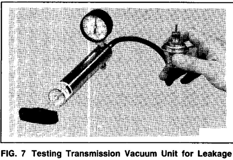
To check the vacuum unit for diaphragm leakage, remove the unit from the transmission. Use a distributor tester equipped with a vacuum pump (Fig. 7). Set the regulator knob until the vacuum gauge reads 18 inches with the end of the vacuum hose blocked off.
Connect the vacuum hose to the manifold vacuum port as shown in Fig. 7. If the gauge still reads 18 inches, the vacuum unit diaphragm is not leaking. A second leakage check can be made as the hose is removed from the transmission vacuum unit. Hold a finger over the end of the control rod. When the hose is removed, the internal spring of the vacuum unit should push the control rod outward. If the vacuum diaphragm needs replacing, install a new unit that has been released for service. Vacuum diaphragm assembly identification .